2-17
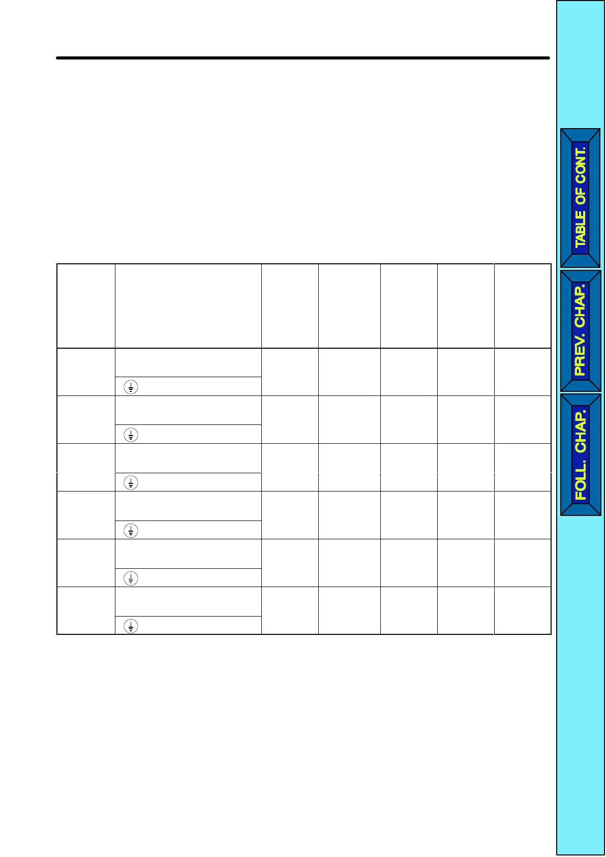
2-2-4 Wiring around the Main Circuit
H Wire
Size, T
erminal Screw, Screw T
ightening T
orque, and
Molded-case Circuit Breaker Capacities
•For the main circuit and ground, always use 600-V polyvinyl chloride
(PVC) cables.
•If
any cable is long and may cause voltage drops, increase the wire size according to
the cable length.
D 3-phase 200-VAC Model
Model
3G3JV-
Terminal symbol Termi-
nal
screw
Screw
tighten-
ing
torque
(NSm)
Wire
size
(mm
2
)
Recom-
mended
wire
size
(mm
2
)
Molded-
case
circuit
breaker
capac-
ity (A)
A2001
R/L1, S/L2, T/L3, –, +1,
+2, U/T1, V/T2, W/T3
M3.5 0.8 to 1.0 0.75 to 2 2 5
A2002
R/L1, S/L2, T/L3, –, +1,
+2, U/T1, V/T2, W/T3
M3.5 0.8 to 1.0 0.75 to 2 2 5
A2004
R/L1, S/L2, T/L3, –, +1,
+2, U/T1, V/T2, W/T3
M3.5 0.8 to 1.0 0.75 to 2 2 5
A2007
R/L1, S/L2, T/L3, –, +1,
+2, U/T1, V/T2, W/T3
M3.5 0.8 to 1.0 0.75 to 2 2 10
A2015
R/L1, S/L2, T/L3, –, +1,
+2, U/T1, V/T2, W/T3
M3.5 0.8 to 1.0 2 to 5.5 2 20
A2022
R/L1, S/L2, T/L3, –, +1,
+2, U/T1, V/T2, W/T3
M3.5 0.8 to 1.0 2 to 5.5 3.5 20
Design Chapter
2
 Loading...


