38
Section 2 INSTALLATION & CONNECTION
ZFV
User’s Manual
Section 2
Sensor Head
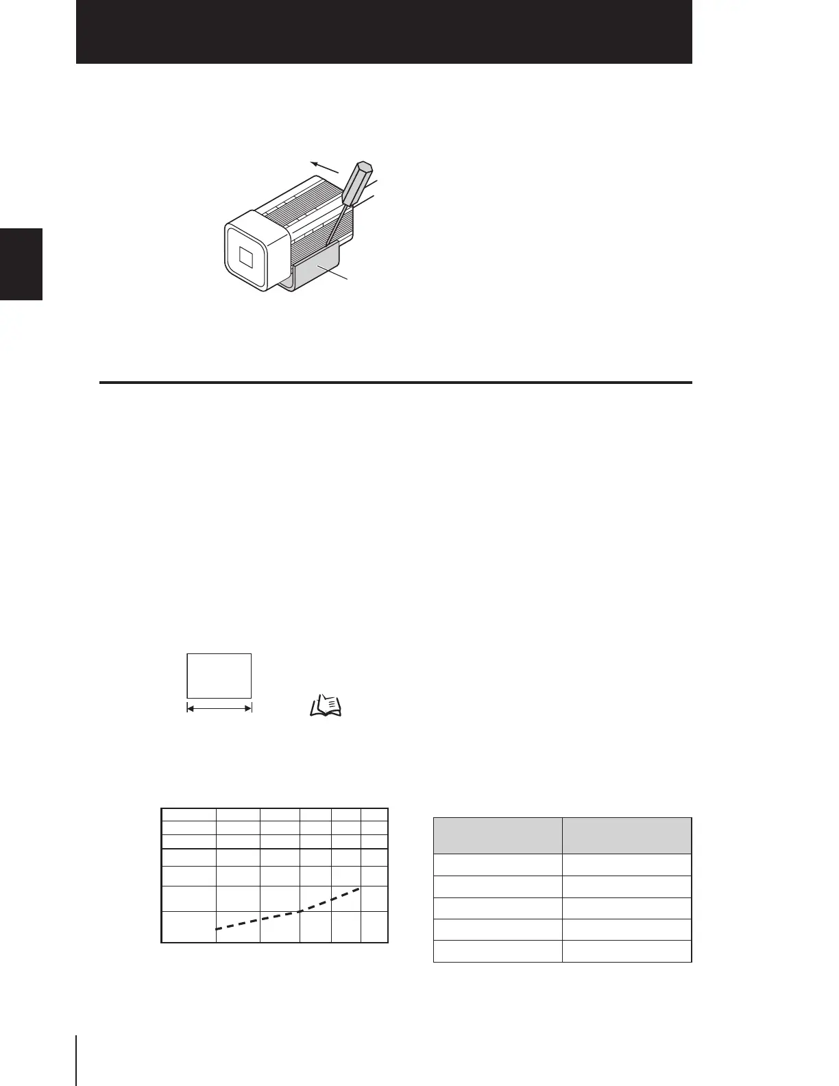
■ Removal procedure
Insert a regular screwdriver into the gap (one of the two gaps) between the mounting
fixture and the Sensor Head case, and remove the mounting fixture.
Installing the Sensor Head
This section describes how to install the Sensor Head.
The detection range of the Sensor Head can be confirmed by the guide light. Install so that
the part to be inspected is inside the frame formed by the guide light.
■ Installation distance
The following graphs show the relationship between detection range and setting dis-
tance for each model of Sensor Head.
Values differ according to each model of Sensor Head, so fully check the model before
using these graphs.
Reading graphs
"H" refers to the following width.
• ZFV-SR10
Detection range H
(mm)
Setting distance L
(mm)
534
637
740
844
949
Mounting fixture
Detection
range
(H)
Details of detection range
p.84
30
100
410
Setting distance L (mm)
Detection range H (mm)

 Loading...