6
Before operating this unit
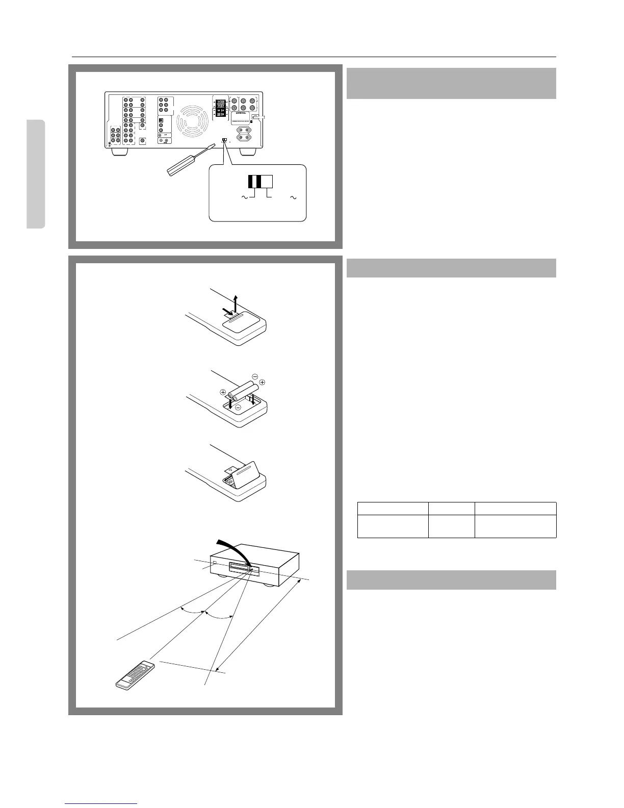
Worldwide models are equipped with a voltage selector to con-
form with local power supplies. Be sure to set this switch to
match the voltage of the power supply in your area before plug-
ging in the unit.
1. Determine the proper voltage for your area: 220-230V or
120V.
2. If the preset voltage is not correct for your area, insert a
screwdriver into the groove in the switch. Slide the switch
all the way to the right (120V) or to the left (220-230V),
whichever is appropriate.
1. Remove the battery compartment cover by pressing and
sliding it out.
2. Insert two AA (R6- or UM-3)-size batteries into the battery
compartment. Carefully follow the polarity diagram (positive
(+) and negative (–) symbols) inside the battery compartment.
3. After batteries are installed and seated correctly, replace
the compartment cover.
•
If the battery voltage is low, the indicator on the remote
controller will not flash when you press any button on the
controller.
Remove low-voltage batteries immediately to avoid dam-
age due to corrosion. Never mix old and new batteries.
•
The learned codes are retained, even when the batteries
are replaced.
They may be lost, however, if battery replacement is not
completed within one hour. In this case, the unit must
learn the codes again.
•
The manganese batteries supplied with this unit have a ser-
vice life of approximately six months, depending on the
frequency of use.
•
Use spare batteries of the type specified in the table below.
We recommend that long-life AA (LR6 or AM-3) size
alkaline batteries be used.
The STAND-BY indicator lights up when the unit receives a
signal from the remote controller.
The following information will help you get optimal use
from the remote controller.
•
Place this amplifier away from direct bright light, which
could prevent proper operation of the remote control.
•
Make sure audio rack doors do not have tinted glass.
Placing the amplifier behind such a door may prevent
proper remote controller operation.
•
Using other remote controllers along with the amplifier’s
remote controller in the same room may cause interference.
Setting the Voltage selector (Worldwide
models only)
Installing the batteries
Type Voltage Size
Manganese or
Alkaline
1.5V
AA, R6 (UM-3) or
LR6 (AM-3)
Using the remote controller
R
V
L
OUT
IN
VIDEO-1
OUT
IN
VIDEO-2
OUT
IN
OUT
IN
IN
IN
TAPE-1
TAPE-2
DVD
R
L
R
L
R
L
R
L
FRONT
SPEAKERS
MAIN
CENTER
SPEAKER
SURROUND SPEAKERS
V
OUT
(REC)
IN
(PLAY)
OUT
(REC)
IN
(PLAY)
MONITOR
OUTPUT
SUBWOOFER
PRE OUT
FRONT REMOTE SPEAKERS
GND
FRONT
DIGITAL INPUT
DIGITAL 1
(OPTICAL)
DIGITAL 2
(COAXIAL)
OUT
IN
REMOTE CONTROL
SURROUND
CENTER SUBWOOFER
DIGITAL 3
(COAXIAL)
MULTI
CHANNEL
INPUT
L
R
R
L
CAUTION: SPEAKER IMPEDANCE
6 OHMS MIN. / SPEAKER
VOLTAGE SELECTOR
MODEL NO.
A-DS650
SWITCHED
TOTAL 100W
AC OUTLETS
MAX.
220-230V
120V
R
L
PHONO
CD
R
L
TUNER
220-230V
VOLTAGE SELECTOR
120V
3
2
1
A-DS650
STAND-BY indicator
Remote control sensor
30˚
30˚
approx. 5 m
(16 feet)
 Loading...