25
English
Command
Command Parameter Control details
PON None Power ON
POF None Power OFF
AVL
***
Volume000‒100
AMT
0 Audio MUTE OFF
1 Audio MUTE ON
IMS
None Input select (toggle)
HM1
HDMI 1 input
(HDMI1)
HM2
HDMI 2 input
(HDMI2)
DV1
DVI-D IN input
(DVI-D)
PC1 PC IN input (PC)
VD1 AV IN input (VIDEO)
UD1 USB input (USB)
MV1
“Memory viewer”
input
(MEMORY VIEWER)
DAM
None
Screen mode select
(toggle)
FULL Full
NORM Normal
NATV Native
HFIT H fit
VFIT V fit
ZOOM Zoom1
ZOM2 Zoom2
Note
●
If multiple commands are transmitted, be sure to wait
for the response for the first command to come from
this unit before sending the next command.
●
If an incorrect command is sent by mistake, this unit
will send an “ER401” command back to the computer.
●
When sending a command which does not require
parameter, a colon (:) is not needed.
●
Consult your local Panasonic dealer for detail
instructions on command usage.
For more details, visit the following web site.
https://panasonic.net/cns/prodisplays/
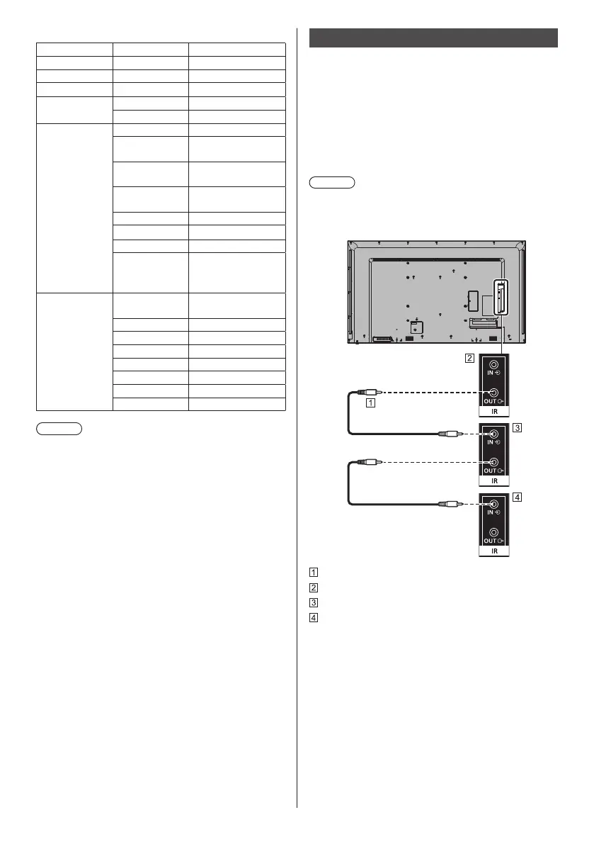
IR IN / IR OUT terminal connection
Connect the mini plug (M3) cable from the IR OUT
terminal of the first display to the IR IN terminal of the
second display.
The infrared signal of the first display is sent to the
second display.
In this case, the IR (infrared ray reception on the remote
control sensor) on the second display does not operate.
Repeating the above connections enables the daisy
chain connection.
Note
●
Connection cables are not supplied with this unit.
●
Daisy chain connection is possible only between the
displays of the same series.
Stereo mini plug (M3) cable (commercially available)
First display
Second display
Third display
 Loading...