9-5
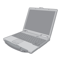
14. Remove the 2 Screws <N19>, and remove the DIMM
Holder.
15. Remove the Tape.
16. Disconnect the 3 Cables from the 3 Connectors.
(CN9,CN14,CN23)
17. Remove the 7 Screws <N19>, and remove the Main PCB
and Combo Socket.
Screws <N3> : DFHE5108ZA
Screws <N8> : DRSB2+10FKL
Screws <N9> : DRSB2+5FKL
Screws <N19> : XSB2+3FNL
9.1.10. Removing the I/O PCB Ass'y
1. Remove the 4 D-SUB Screws <N2>.
2. Remove the 2 Screws <N9>.
3. Remove the I/O PCB Ass'y.
Screws <N2> : DFHE5058ZB
Screws <N9> : DRSB2+5FKL
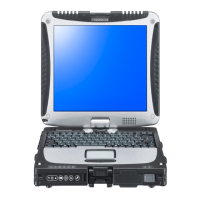
9.1.11. Removing the Power SW PCB
1. Remove the Screw <N1>.
2. Disconnect the Cable from the Connector (CN9).
3. Remove the Power SW PCB.
Screw <N1> : DFHE5025XA
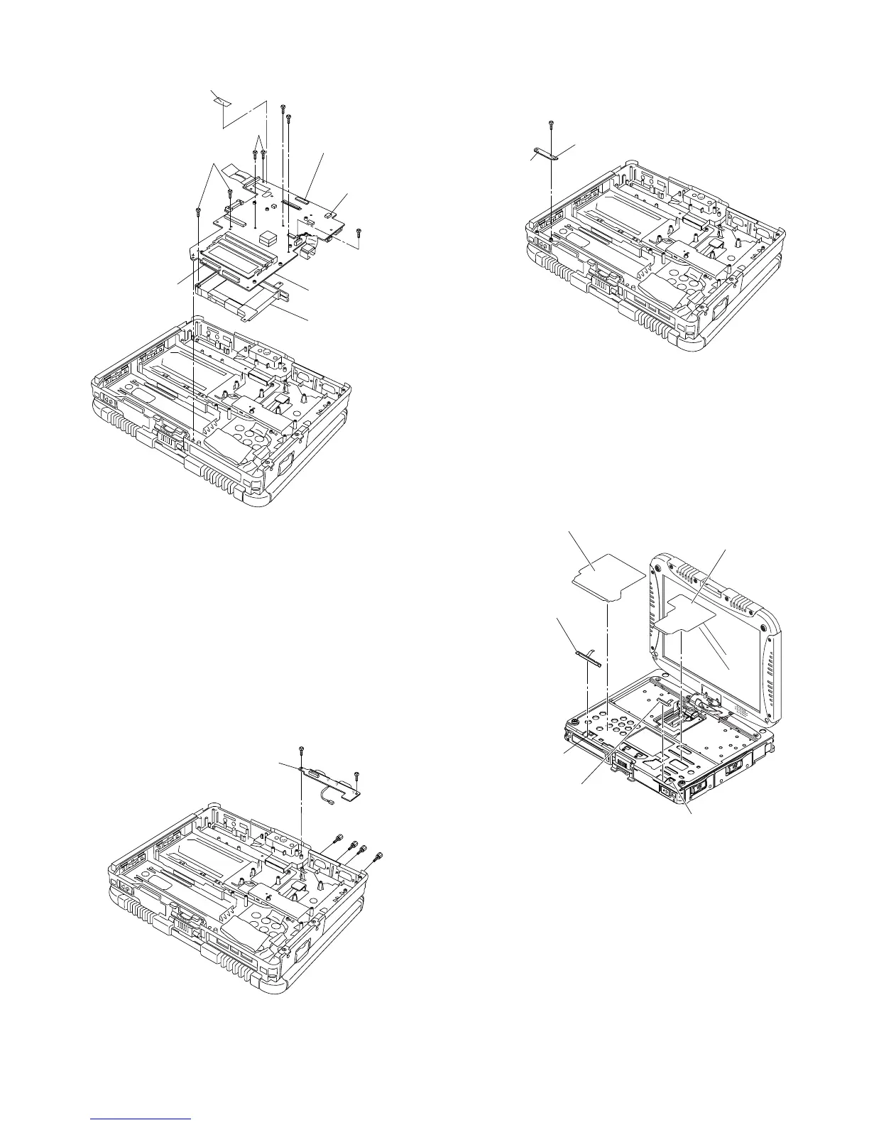
9.1.12. Removing the left LED and right
LED PCB
1. Remove the two Release Papers.
2. Disconnect the Cable from the Connector (CN806).
3. Remove the left LED PCB.
4. Disconnect the Cable from the Connector (CN801).
5. Remove the right LED PCB.
<N19>
<N19>
<N19>
<N19>
<N19>
Tape
Main PCB
Combo Socket
Connector(CN9)
Connector(CN14)
Connector(CN23)
<N9>
<N2>
<N2>
<N2>
<N2>
<N9>
I/O PCB Ass’y
<N1>
Connector(CN9)
Power SW
PCB
Release Paper
Release Paper
left LED PCB
right LED PCB
Connector(CN801)
Connector(CN806)
 Loading...