Adjustment
13 - 35
5
4
2
6
1
7
3
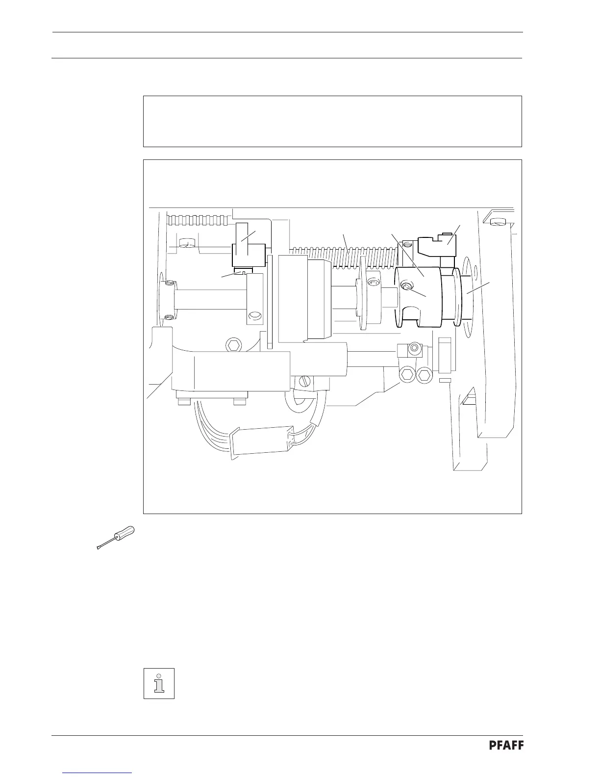
Fig. 13 - 31
13.07.02 Control cam to bobbin opener and tripping lever
Requirements
1. Control cam 2 must be touching bearing collar 3.
2. The roller of tripping lever 6 must fall slightly into the path of control cam 2.
● Loosen screws 1 and bring control cam 2 to rest against bearing collar 3.
● In this position tighten one of the screws 1 slightly so that control cam 2 can still be
turned.
● Loosen screw 4.
● Bring the needle bar to BDC and position the straight section of the cam track under the
roller of tripping lever 6.
● Activate the engaging lever by hand.
● Move tripping lever 6 together with schaft 7 in accordance with requirement 2.
● Taking care to ensure that connecting link 5 engages completely in the groove of the
rack, bring connecting link 5 to rest on the right and tighten screw 4.
Only tighten screws 1 slightly for the following adjustment.
 Loading...