Adjustment
13 - 42
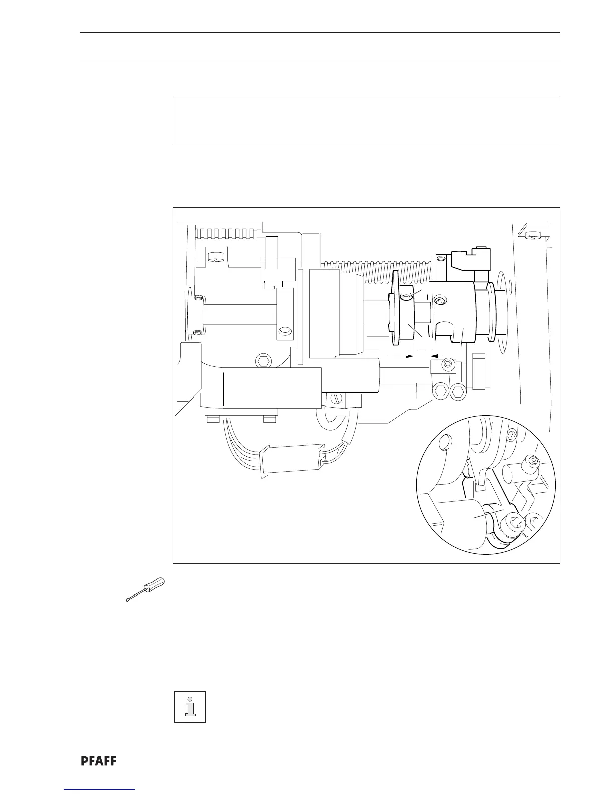
13.07.09 Control cam in relation to scissor
Requirements
1. The cutting motion must begin when the needle bar is 0.6 mm after TDC.
2. There must be a clearance of 9 mm between control cams 2 and 4.
● Loosen screws 1.
● Bring the needle bar to BDC and activate the engaging lever by hand.
● Bring the needle bar to 0.6 mm after TDC ( use adjustment gauge and C-clamp ).
● Turn control cam 2 until the trip is touching the roller of the tripping lever 3.
● Taking care that control cam 2 is 9 mm from retractor cam 4, tighten one of the
screws 1.
● Remove the C-clamp, make the second screw 1 accessible and tighten it.
When using elastic sewing threads it can be necessary to set the relationship
between the control cam and the bobbin opener and the scissors a little „later“.
A thread tension control ( subclass 906/10) is available for automatic tension-
release with highly elastic sewing threads.
9 mm
4
1
2
3
Fig. 13 - 38
 Loading...