Adjustment
13 - 44
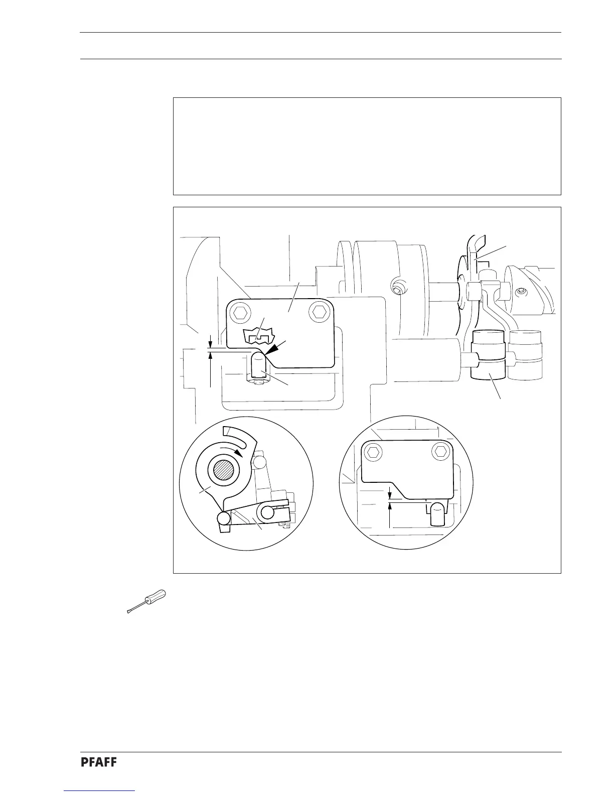
13.07.11 Scissor return control
Requirements
1. When the point of the trip of control cam 1 is exactly at the roller of tripping lever 2 and
trip 3 is touching the beginning of the angular edge of guide plate 5 ( see arrow ) there
must be a clearance of approx. 0.6 mm between trip 3 and guide plate 5.
2. When the rock shaft has sprung back to its starting position the maximum clearance
between trip 3 and guide plate 5 must be 0.3 mm.
● Position the point of the trip of control cam 1 exactly at the roller of tripping lever 2 by
turning the handwheel.
● Move trip 3 ( screw 4 ) in accordance with requirement 1.
● Bring rock shaft back to its starting position.
● Check requirement 2. If necessary, position guide plate 5 appropriately.
3
5
1
2
0.6 mm
4
1
2
0.3 mm
Fig. 13 - 40
 Loading...