Adjustment
13 - 41
6
5
2
4
3
1
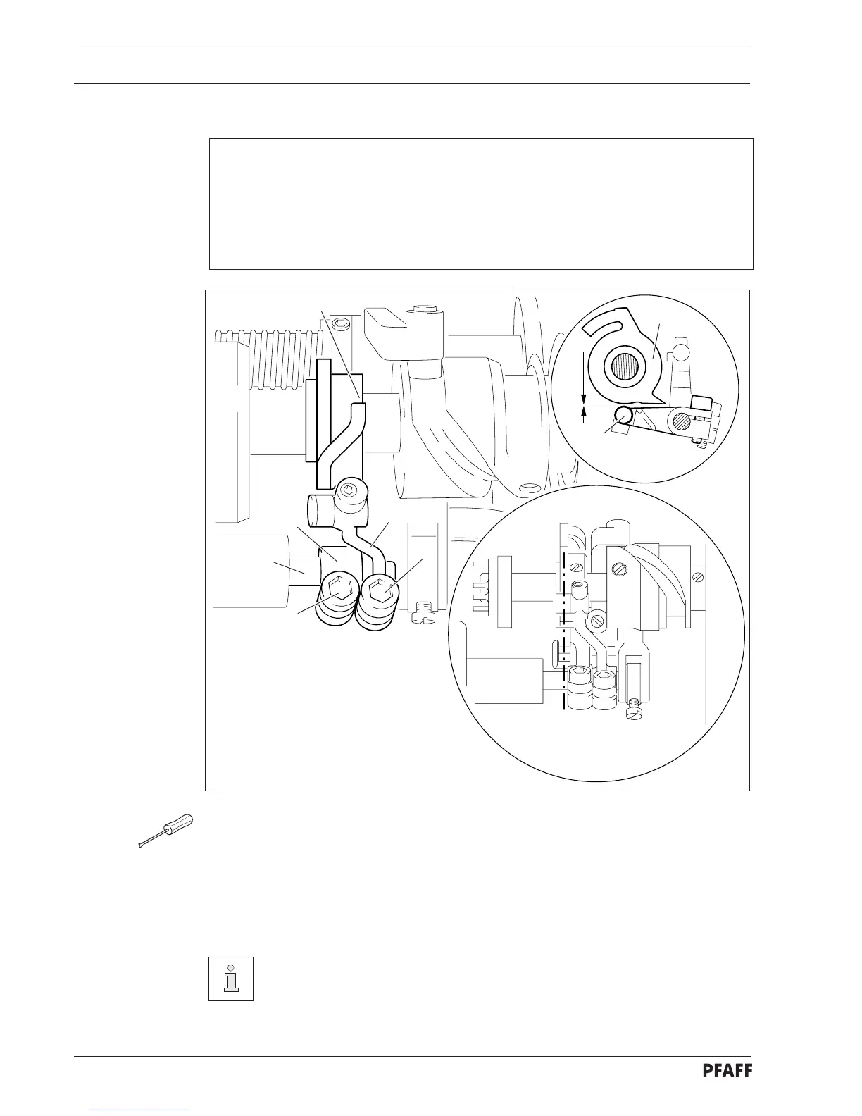
0.3 mm
6
4
Fig. 13 - 37
● Bring the needle bar to BDC and activate the tripping lever by hand.
● Loosen screws 1 and 2.
● Turn the handwheel in the direction of rotation until rock shaft 3 is at its left point of
reversal.
● Move tripping lever 4 and back-racking lever 5 in accordance with requirement 1.
● Turn tripping lever 4 in accordance with requirement 2.
● In this position and observing requirement 1, tighten screw 1.
Screw 2 remains loosened for the following adjustment.
13.07.08 Scissor tripping-lever in relation to the control cam of the scissor
Requirements
At the left point of reversal of the rock shaft 3
1. the roller of tripping lever 4 and the roller of back-racking lever 5 must be in the middle
of control cam 6 and
2. there must be a distance of 0.3 mm between the roller of tripping lever 4 and the
external circumference of control cam 6.
 Loading...