19
Connecting your equipment
03
Connecting your equipment
This receiver provides you with many connection possibilities, but it doesn’t have to be difficult. This chapter
explains the kinds of components you can connect to make up your home theater system.
CAUTION
! Before making or changing the connections, switch off the power and disconnect the power cord from the
power outlet. Plugging in should be the final step.
! When making connections, also keep the power cords of the devices being connected unplugged from the
power outlets.
! Depending on the device being connected (CD, DVD or BD player, etc.), the methods of connection and ter-
minal names may differ from the explanations in this manual. Also refer to the operating instructions of the
respective devices.
Important
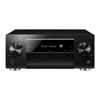
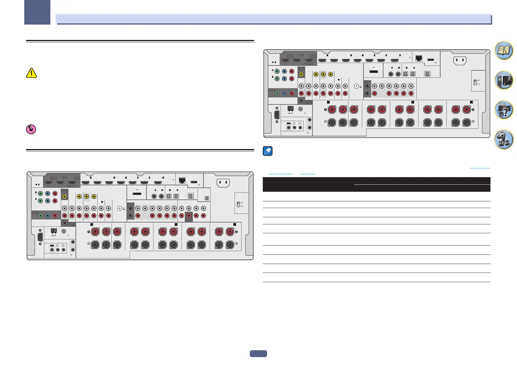
! Illustration shows the SC-LX88, however connections for the SC-LX78 are the same except where noted.
Rear panel
SC-LX88
OUT
IN
AC IN
LAN
(
10/100
)
DC OUTPUT
for WIRELESS LAN
(
OUTPUT 5 V
0.6 A MAX
)
(
OUTPUT 5 V
0.9 A MAX
)
(
OUTPUT 12 V
TOTA L 150 mA MAX
)
OPTICALCOAXIAL
ASSIGNABLE
ASSIGNABLE ASSIGNABLE
PRE OUTMULTI CH IN
VIDEO
AUDIO
ZONE 2
SUBWOOFER
1
1
IN
2
2
SURROUND SURR BACK
T.MIDDLE
(Single)
(Single)
FRONT CENTER
SUBWOOFER
1
2
L
R
DVR/BDR
IN
ZONE 3
OUT
ZONE 2
OUT
SAT/CBL
IN OUT
MONITOR
OUT
MONITOR
OUT
P
B
Y
P
R
ANTENNA
AM LOOP FM UNBAL 75
RS-232C
IR
12V TRIGGER
SPEAKERS
FRONTCENTER
A AB
RL
SURROUND
RL
SURROUND BACK
RL
TOP MIDDLE
RL
IN
1
(
CD
)
PHONO
IN
IN
1
(
DVD
)
BD IN
IN
2
(
SAT/CBL
)
IN
3
(
DVR/BDR
)
IN
6
IN
4
IN
7
/MHL
IN
1
(
TV
)
IN
2
(
DVR/BDR
)
IN
1
(
DVD
)
IN
2
(
SAT/CBL
)
IN
1
(
DVD
)
IN
2
(
DVR/
BDR
)
OUT
F WIDE
FRONT WIDE /
RL
SIGNAL
GND
OUT 3
(HDZONE)
OUT 2OUT 1
(CONTROL)
SELECTABLE
COMPONENT VIDEO
HDMI
ASSIGNABLE
1
-
7
ASSIGN-
ABLE
USB-DAC
IN
SUBWOOFER
SURR BACKSURROUND
CENTERFRONT
L
R
LIVENEUTRAL
(
OUTPUT 5 V 0.1 A MAX
)
ADAPTER PORT
220 - 230 V
240 V
VOLTAGE
SELECTOR
SC-LX78
OUT
IN
AC IN
LAN
(
10/100
)
DC OUTPUT
for WIRELESS LAN
(
OUTPUT 5 V
0.6 A MAX
)
(
OUTPUT 5 V
0.9 A MAX
)
(
OUTPUT 12 V
TOTA L 150 mA MAX
)
(
OUTPUT 5 V 0.1 A MAX
)
OPTICALCOAXIAL
ASSIGNABLE
ASSIGNABLE ASSIGNABLE
ADAPTER PORT
PRE OUT
VIDEO
AUDIO
ZONE 2
SUBWOOFER
1
1
IN
2
2
SURROUND SURR BACK
T.MIDDLE
(Single)
(Single)
FRONT CENTER
SUBWOOFER
1
2
L
R
DVR/BDR
IN
ZONE 3
OUT
ZONE 2
OUT
SAT/CBL
IN OUT
MONITOR
OUT
MONITOR
OUT
P
B
Y
P
R
ANTENNA
AM LOOP FM UNBAL 75
RS-232C
IR
12V TRIGGER
SPEAKERS
FRONTCENTER
A AB
RL
SURROUND
RL
SURROUND BACK
RL
TOP MIDDLE
RL
IN
1
(
CD
)
PHONO
IN
IN
1
(
DVD
)
BD IN
IN
2
(
SAT/CBL
)
IN
3
(
DVR/BDR
)
IN
6
IN
4
IN
7
/MHL
IN
1
(
TV
)
IN
2
(
DVR/BDR
)
IN
1
(
DVD
)
IN
2
(
SAT/CBL
)
IN
1
(
DVD
)
IN
2
(
DVR/
BDR
)
OUT
F WIDE
FRONT WIDE /
RL
SIGNAL
GND
OUT 3
(HDZONE)
OUT 2OUT 1
(CONTROL)
SELECTABLE
COMPONENT VIDEO
HDMI
ASSIGNABLE
1
-
7
L
R
ASSIGN-
ABLE
LIVENEUTRAL
220 - 230 V
240 V
VOLTAGE
SELECTOR
Notes
! The RS-232C terminal is exclusively for the installer.
! The input functions below are assigned by default to the receiver’s different input terminals. Refer to The Input
Setup menu on page 52 to change the assignments if other connections are used.
Input function
Input Terminals
HDMI Audio Component
BD
(BD)
DVD IN 1 COAX-1 IN 1
SAT/CBL IN 2 COAX-2
DVR/BDR IN 3 OPT-2 IN 2
HDMI 4 IN 4
HDMI 5
(front panel)
IN 5
HDMI 6 IN 6
HDMI 7/MHL IN 7
TV OPT-1
CD ANALOG-1
 Loading...