Using Events, Logic, And IR
9 - 33
If there are user min and max fader limits set on the “Amplifier” channel, then
those limits will be used automatically with the map event.
Gating Information Sent To A Control System
In this example, a logic output will be used to indicate that a particular micro-
phone has gated on. When the gate status changes, the logic output will
change and the SoundStructure system will send a command acknowledge-
ment that could be used by a control system to indicate that a microphone has
gated on.
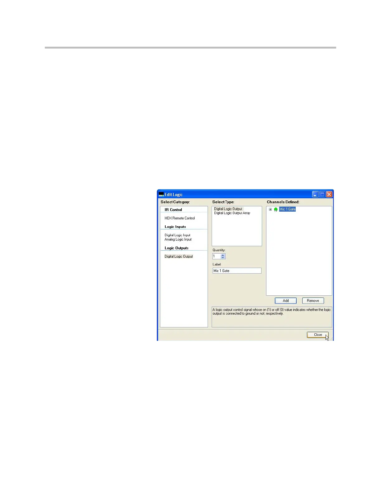
Step 1: Add the Logic Output pin
In this example, a single logic output pin called “Mic 1 Gate” is created. Check
the wiring page and the logic connections to a desired logic output pin if
required.