Design Guide for the Polycom SoundStructure C16, C12, C8, and SR12
13 - 70
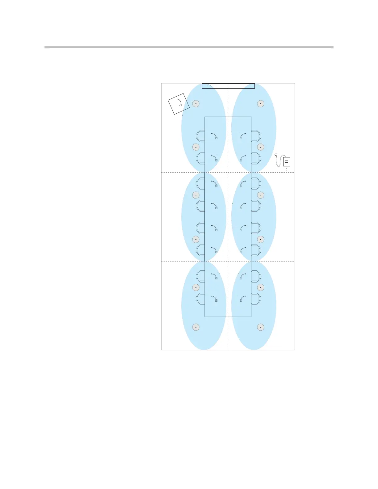
The next step is to create the microphone zone groups that will simplify setting
up the reinforcement levels. The designed zones are shown in the following
figure.
As part of the design process, the appropriate reinforcement levels would be
determined and a mapping similar to the one shown in the following figure
would be created as the baseline reinforcement in the room. This mapping
shows how the different input zones will be mapped to the different amplifier
Lectern
Zone 1
Zone 2
Zone 3
Zone 6
Zone 5
Zone 4
A
Mic 1
Display
Mic 2
Mic 3
Mic 4
Mic 5
Mic 6
Mic 7
Mic 8
Mic 16
Mic 15
Mic 14
Mic 13
Mic 12
Mic 11
Mic 10
Mic 9
Mic
c
Mi
Mic
ABC ABC
ABC ABC
ABC ABC
ABC ABC
ABC ABC
ABC ABC
 Loading...