Chapter 3 Hardware Configuration
SE-8134 SERIES USER MANUAL
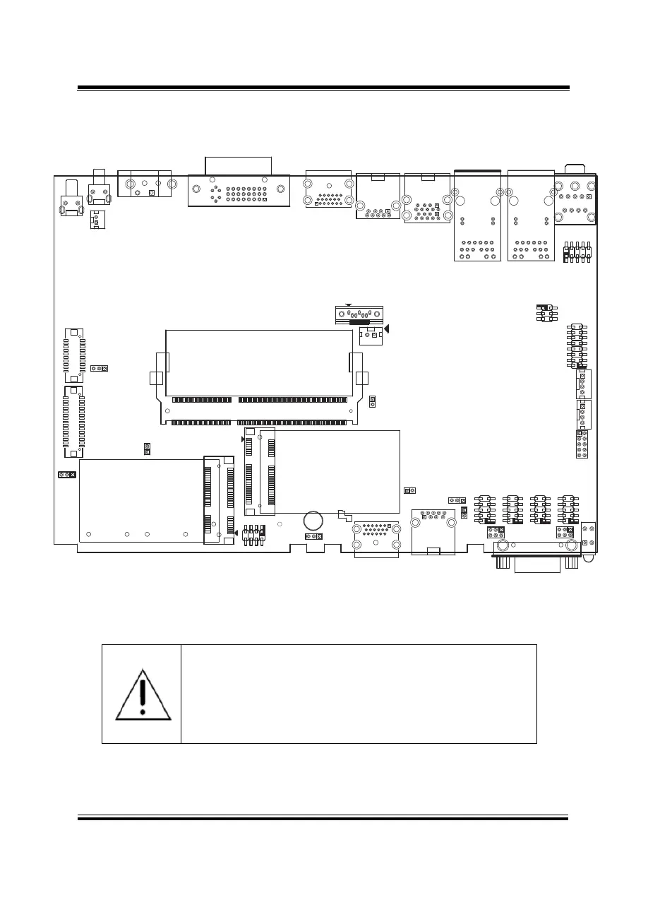
3.2 COMPONENT LOCATIONS OF SYSTEM MAIN BOARD
3.2.1 Top View of System Main Board
Figure 3-1. Main Board Component Location (Top View)
WARNING: Always disconnect the power cord when you are
working with connectors and jumpers on the main board.
Make sure both the system and peripheral devices are
turned OFF as sudden surge of power could damage
sensitive components. Make sure SE-8134 is properly
grounded.
JP_VDD1
3
1
JP7
20 19
1
1
2930
2
1
1
2
2
3
LVDS1
JINV1
JP6
PWR_BTN1
J_PBTN1
RST1
CN_POWER1
DVI1
HDMI1
USB2 USB1
LAN1 LAN2
AUDIO1
JDIO1
JP_I2C1
JPOE1
JI2C1
JI2C2
JLPC1
COM4
COM1
COM2COM3
LED1
JP_COM1
DIO1
JP_COM2
USB3
HDMI2
JP_ATX1
JP_TPM1
JP8
JP_EDP1
JP10
SO_DIMM1
M_SATA1
M_PCIE1
JP4
SATA_PWR1
SATA1
1
2
16
18
52
51
17
15
16
18
52
2
1
17
15
51
13
1
19
1
9 5
4
1 2
1
3
1
2
1
2
5
6
6
6
6
1
1
6
1
1
10
5
10 10
10
5 5 5
1
6
5
2
2
1
3 4
1
1
1
1
9
1
2
7
8
10
4
4
2
2
1516
1
2
5 6
1
2
9
10
1
2 3 54
25
22
R16
R14
R16
R14
R15
R13
R15
R13
R1
R7
R6
R12
R1
R7
R6
R12
L1
L2
L3
L4 L2 L3L1 L4
A1
A9
B1
B9
A4
A5
B4
B5
1
9
4
5
1
19
1
9
17
8
16
24
1
2
3
3
1
1
2
2
4
4
1
2
1
2
72
71
74
73
204
203
1
2
1 2
1
7
 Loading...