EasyManuals Logo
Home>protech>Computer Hardware>SE-8134

protech SE-8134 User Manual

Default Icon
130 pages
To Next Page IconTo Next Page
To Previous Page IconTo Previous Page
Page #25 background imageLoading...
Page #25 background image
Chapter 3 Hardware Configuration
SE-8134 SERIES USER MANUAL
3.4 Setting Main Board Connectors and Jumpers
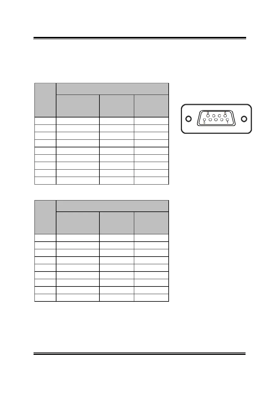
3.4.1 COM Connector
Connector Location: COM1, COM2, COM3, COM4
Description: COM Connector
COM1(RS232/RS422/RS485) Connector Pin Assignment:
PIN
ASSIGNMENT
RS232
(Default Setting)
RS422
RS485
1
COM2_DCD
TX-
D-
2
COM2_RX
TX+
D+
3
COM2_TX
RX-
X
4
COM2_DTR
RX+
X
5
GND
GND
GND
6
COM2_DSR
X
X
7
COM2_RTS
X
X
8
COM2_CTS
X
X
9
COM2_RI
*1
X
X
COM2(RS232/RS422/RS485) Connector Pin Assignment:
PIN
ASSIGNMENT
RS232
(Default Setting)
RS422
RS485
1
COM2_DCD
TX-
D-
2
COM2_RX
TX+
D+
3
COM2_TX
RX-
X
4
COM2_DTR
RX+
X
5
GND
GND
GND
6
COM2_DSR
X
X
7
COM2_RTS
X
X
8
COM2_CTS
X
X
9
COM2_RI
*1
X
X
Notes:
1. COM1 and COM2 pin 9 are selectable for RI, +5V or +12V by jumper setting.
Default setting is RI, please see “COM1 and COM2 PIN9 Definition Selection
Guide” for selection details
2. COM1,COM2 is selectable as RS232, RS422, RS485 by BIOS.
COM1/
COM2

Table of Contents

Questions and Answers:

Question and Answer IconNeed help?

Do you have a question about the protech SE-8134 and is the answer not in the manual?

protech SE-8134 Specifications

General IconGeneral
Brandprotech
ModelSE-8134
CategoryComputer Hardware
LanguageEnglish

Related product manuals