LTE Standard Module Series
EC21_Series_Hardware_Design
40
/ 118
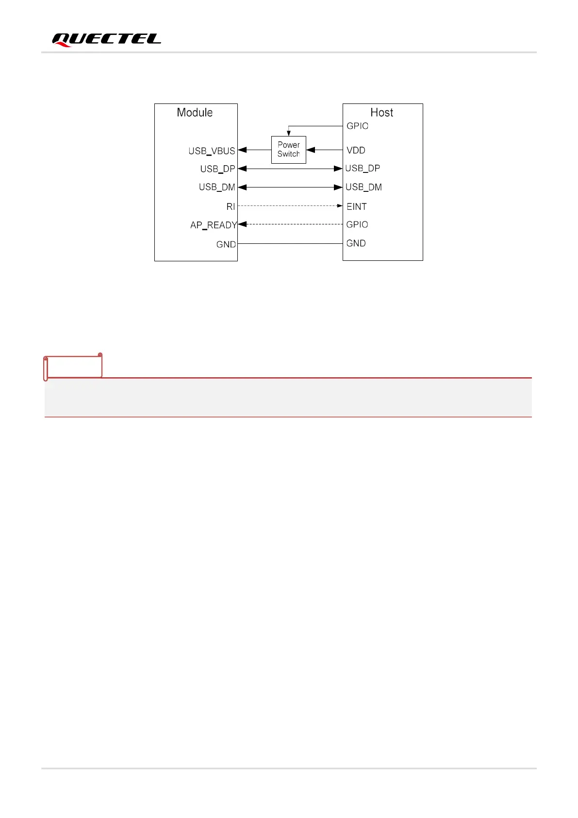
The following figure shows the connection between the module and the host.
Figure 6: Sleep Mode Application Without Suspend Function
Switching on the power switch to supply power to USB_VBUS will wake up the module.
Pay attention to the voltage-level matching of the circuit in dotted line between the module and the host.
For more details about EC21 series power management application, see document [4].
3.5.2. Airplane Mode
When the module enters airplane mode, the RF function will be disabled, and all AT commands related
to it will be inaccessible. This mode can be set via the following ways.
Hardware:
The W_DISABLE# pin is pulled up by default. Driving it to low level will let the module enter airplane
mode.
Software:
AT+CFUN=<fun> provides the choice of the functionality level through setting <fun> into 0, 1 or 4.
AT+CFUN=0: Minimum functionality mode. Both (U)SIM and RF functions are disabled.
AT+CFUN=1: Full functionality mode (by default).
AT+CFUN=4: Airplane mode. RF function is disabled.
NOTE

 Loading...


