LTE Standard Module Series
EC21_Series_Hardware_Design
48
/ 118
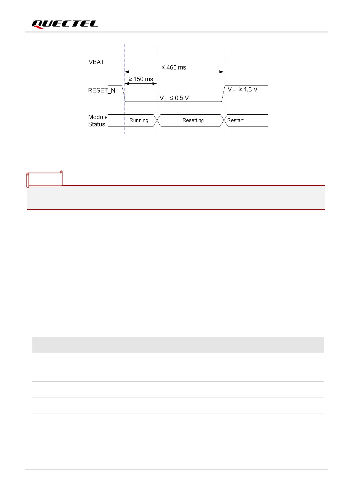
Figure 16: Reset Timing
1. Use RESET_N only when failed to turn off the module by AT+QPOWD and PWRKEY pin.
2. Ensure that there is no large capacitance on PWRKEY and RESET_N pins.
3.9. (U)SIM Interface
The (U)SIM interface circuitry meets ETSI and IMT-2000 requirements. Both 1.8 V and 3.0 V (U)SIM
cards are supported.
Table 10: Pin Definition of (U)SIM Interface
Pin Name Pin No. I/O Description Comment
USIM_VDD 14 PO (U)SIM card power supply
Either 1.8 V or 3.0 V is
supported by the module
automatically.
USIM_DATA 15 DIO (U)SIM card data
USIM_CLK 16 DO (U)SIM card clock
USIM_RST 17 DO (U)SIM card reset
USIM_
PRESENCE
13 DI (U)SIM card insertion detect
1.8 V power domain.
If unused, keep it open.
NOTE

 Loading...


