EasyManua.ls Logo

Quectel EC21 Series User Manual

Quectel EC21 Series
122 pages
To Next Page IconTo Next Page
To Previous Page IconTo Previous Page
Page #43 background image
LTE Standard Module Series
EC21_Series_Hardware_Design
42
/ 118
Figure 7: Power Supply Limits during Burst Transmission
To decrease voltage-drop, use bypass capacitors of at least 100 µF with low ESR, and reserve a multi-
layer ceramic chip capacitor (MLCC) array due to their low ESR. It is recommended to use at least three
ceramic capacitors (100 nF, 33 pF, 10 pF) for composing the MLCC array, and place these capacitors
close to VBAT_BB and VBAT_RF pins. The main power supply from an external application has to be a
single voltage source and can be expanded to two sub paths with star structure. The width of VBAT_BB
trace should be no less than 1 mm; and the width of VBAT_RF trace should be no less than 2 mm. In
principle, the longer the VBAT trace is, the wider it will be.
In addition, in order to avoid the damage caused by electric surge and ESD, it is suggested that a TVS
diode with suggested low reverse stand-off voltage V
RWM
4.5 V, low clamping voltage V
C
and high reverse
peak pulse current I
PP
should be used. The following figure shows the star structure of the power supply.
Figure 8: Star Structure of the Power Supply
3.6.3. Reference Design for Power Supply
The performance of the module largely depends on the power source. The power supply should be able

Table of Contents

Question and Answer IconNeed help?

Do you have a question about the Quectel EC21 Series and is the answer not in the manual?

Quectel EC21 Series Specifications

General IconGeneral
CategoryControl Unit
Form FactorLCC
Operating Temperature-40°C to +85°C
Storage Temperature-45°C to +90°C
Power ConsumptionTBD
Network Support (LTE TDD)B38/B40/B41
Network Support (GSM)850/900/1800/1900 MHz
Module TypeLTE Cat 1
Supply Voltage3.3V
InterfaceUSB 2.0
SIM Interface1.8V/3.0V
Data Rate (Downlink)10 Mbps
Data Rate (Uplink)5Mbps
Network Support (LTE FDD)B1/B3/B5/B8/B20
GNSSGPS/GLONASS/BeiDou
CertificationsCE, FCC, GCF, PTCRB

Summary

2 Product Overview

2.2. Key Features

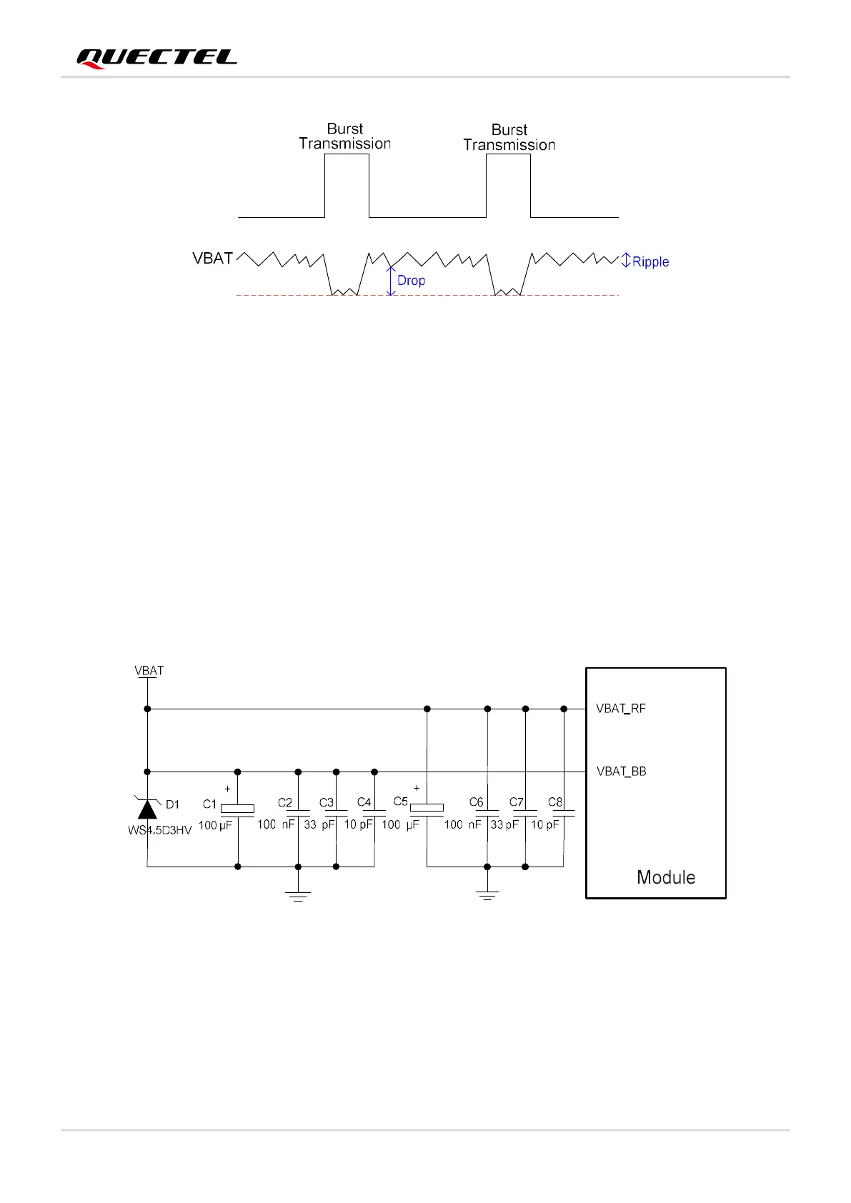
Details key features of the EC21 series module, including power supply and transmission.

3 Application Interfaces

3.2. Pin Assignment

Visual representation of the EC21 series module's pin assignment (top view).

3.3. Pin Description

Detailed description of each pin's I/O type, function, and characteristics.

4 RF Specifications

4.1. Cellular Network

Details antenna interfaces, frequency bands, and operating frequencies for cellular network.

4.2. GNSS

Covers GNSS antenna interface, frequencies, and performance metrics.

5 Electrical Characteristic and Reliability

5.4. Power Consumption

Presents current consumption values for various operating states and conditions.

6 Mechanical Information

6.1. Mechanical Dimensions

Provides the physical dimensions and tolerances of the EC21 module.

6.2. Recommended Footprint

Offers a recommended PCB footprint for the EC21 series module.

7 Storage, Manufacturing and Packaging

7.2. Manufacturing and Soldering

Guides on manufacturing processes, soldering, and thermal profiles.

Related product manuals