LTE Standard Module Series
EC21_Series_Hardware_Design
43
/ 118
to provide sufficient current up to 2.0 A at least. If the voltage drop between the input and output is not
too high, it is suggested that an LDO should be used to supply power for the module. If there is a big
voltage difference between the input source and the desired output (VBAT), a buck converter is preferred
to be used as the power supply.
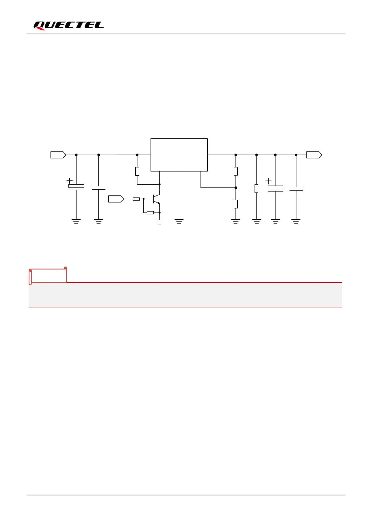
The following figure shows a reference design for +5.0 V input power source. The typical output of the
power supply is about 3.8 V and the maximum load current is 3.0 A.
DC_IN
MIC29302WU
IN OUT
EN
GND
ADJ
2 4
1
3
5
VBAT
100 nF
470 μF
100 nF
100K
47K
470 μF
470R
51K
1 %
1 %
4.7K
47K
VBAT_EN
Figure 9: Reference Circuit of Power Supply
To avoid damaging internal flash, do not switch off the power supply when the module works normally.
Only after the module is shut down by PWRKEY or AT command, then the power supply can be cut off.
3.6.4. Monitor the Power Supply
AT+CBC can be used to monitor the VBAT_BB voltage value. For details of the command, see
document [2]..
3.7. Power-on/off Scenarios
3.7.1. Turn on with PWRKEY
The following table shows the pin definition of PWRKEY.
NOTE

 Loading...


