EasyManua.ls Logo

Quectel EM05-G User Manual

Quectel EM05-G
73 pages
To Next Page IconTo Next Page
To Previous Page IconTo Previous Page
Page #25 background imageLoading...
Page #25 background image
LTE Standard Module Series
EM05-G Hardware Design
EM05-G_Hardware_Design 24 / 69
Current Consumption
Run Time
DRX OFF ON OFF ON OFF ON OFF ON OFF
Figure 3: DRX Run Time and Current Consumption in Sleep Mode
3.2.1.1. USB Application with USB Remote Wakeup Function
If the host supports USB suspend/resume and remote wakeup function, the following two conditions must
be met to make the module enter sleep mode.
Execute AT+QSCLK=1 to enable the sleep mode.
The host’s USB bus, which is connected to the module’s USB interface, enters suspend state.
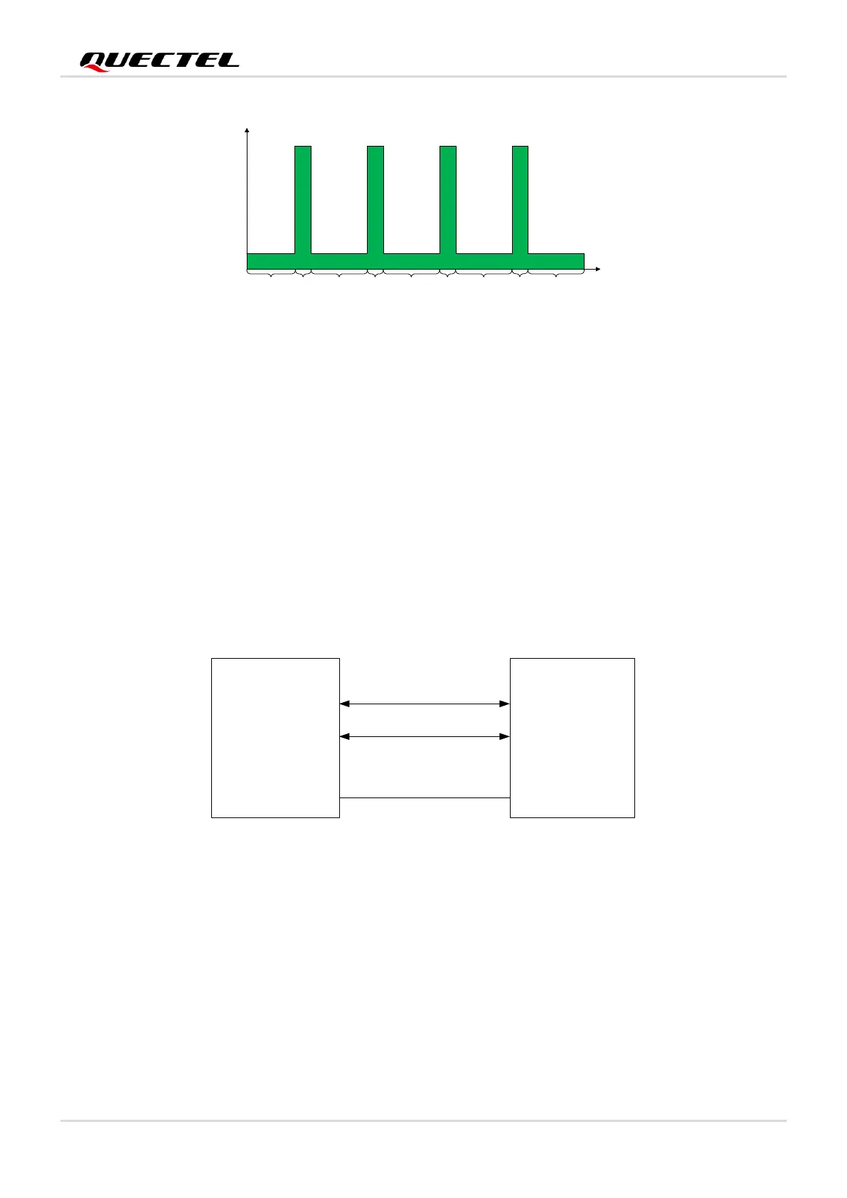
The following figure shows the connection between the module and the host.
USB_DP
USB_DM
USB_DP
USB_DM
Module
Host
GND
GND
Figure 4: Sleep Mode Application with USB Remote Wakeup
The module and the host will wake up in the following conditions:
Sending data to EM05-G via USB will wake up the module.
When EM05-G has a URC to report, the module will send remote wake-up signals via USB bus to
wake up the host.

Table of Contents

Question and Answer IconNeed help?

Do you have a question about the Quectel EM05-G and is the answer not in the manual?

Quectel EM05-G Specifications

General IconGeneral
Operating Temperature-40°C to +85°C
Storage Temperature-40°C to +90°C
Power ConsumptionTBD
Max Downlink Speed150 Mbps
Max Uplink Speed50 Mbps
GSM Bands850/900/1800/1900 MHz
SIM Interface1.8V/3.0V
USB InterfaceUSB 2.0
Firmware UpdateUSB/FOTA
Module TypeLTE Cat 4
Power Supply3.3V to 4.3V
LTE BandsB1/B2/B3/B4/B5/B7/B8/B12/B13/B20/B28/B66
WCDMA BandsB1/B2/B4/B5/B8
GNSSGPS, GLONASS, BeiDou, Galileo
UART InterfaceYes
I2C InterfaceYes
SPI Interface1 x SPI
ADC Interface1 x ADC
PCM InterfaceYes
Networking ProtocolsTCP/UDP/PPP/HTTP/FTP/SSL
CertificationsCE, GCF, PTCRB, FCC
VoiceVoLTE

Summary

Safety Information

Product Concept

Key Features

Lists the main technical features and specifications of the EM05-G module.

Module Pin Configuration

Pin Assignment

Shows the physical layout and numbering of the module's pins.

Pin Description

Details the function, I/O type, and DC characteristics of each pin.

Operating Characteristics

Power Supply

Reference Design for Power Supply

Provides a schematic for a typical power supply circuit.

Turn on

Turn off

Turn off the Module Through FULL_CARD_POWER_OFF#

Details hardware shutdown using the FULL_CARD_POWER_OFF# pin.

Turn off the Module Through AT Command

Explains software shutdown using the AT+QPOWD command.

Reset the Module

Application Interfaces

(U)SIM Interface

Describes the interface for connecting SIM cards.

Pin Definition of (U)SIM

Lists the pins associated with the (U)SIM interface.

USB Interface

Reference Circuit of USB 2.0 Interface

Shows the reference circuit for the USB 2.0 interface.

Control and Indication Interfaces

RF Characteristics

Cellular Antenna Interfaces

Details the module's cellular antenna connectors.

Operating Frequency

Lists the supported frequency bands for WCDMA and LTE.

Receiving Sensitivity

Shows the RF receiving sensitivity performance of the module.

RF Output Power

Details the maximum and minimum RF output power levels.

GNSS Antenna Interface

Antenna Connectors

Antenna Requirements

Reliability, Radio and Electrical Characteristics

Power Supply Requirements

Specifies the required input voltage range for the module.

Current Consumption

Lists typical current consumption values in various operating states.

Electrostatics Discharge

Thermal Dissipation

Absolute Maximum Ratings

Operating and Storage Temperatures

Mechanical Dimensions and Packaging

Mechanical Dimensions of the Module

Provides detailed physical dimensions of the module.

Related product manuals