LTE Standard Module Series
EM05-G Hardware Design
EM05-G_Hardware_Design 38 / 69
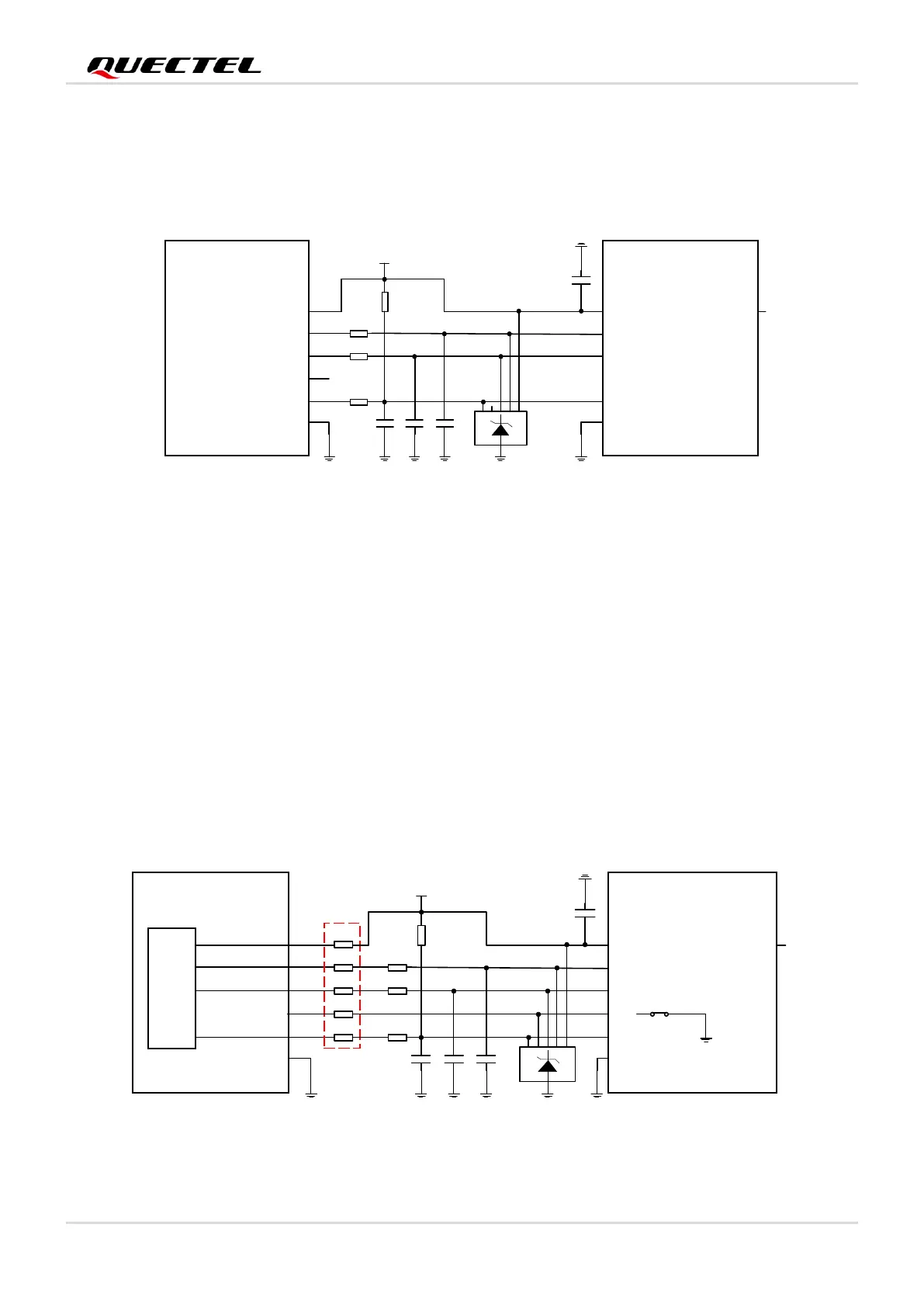
4.1.4. (U)SIM Card Connector Without Hot-plug
If (U)SIM card hot-plug is not needed, keep USIM_DET unconnected. A reference circuit for (U)SIM card
interface with a 6-pin (U)SIM card connector is illustrated by the following figure.
Figure 17: Reference Circuit of (U)SIM Interface with a 6-Pin (U)SIM Card Connector
4.1.5. (U)SIM 2 Card Connector
EM05-G provides two (U)SIM interfaces. (U)SIM1 interface is used for external (U)SIM card only, and
(U)SIM2 interface is used for external (U)SIM card or internal eSIM card. The default function is eSIM.
It should be noted that, when the (U)SIM2 interface is used for an external (U)SIM card, the circuits are
the same as those of (U)SIM1 interface. When the (U)SIM2 interface is used for the internal eSIM card,
pins 40, 42, 44, 46 and 48 of the modules must be kept open.
A recommended compatible design for the (U)SIM2 interface is shown below.
Module (U)SIM Card
Connector
USIM2_DET
USIM2_DATA
USIM2_CLK
RST
CLK
CD
IO
USIM2_VDD
USIM2_VDD
USIM2_RST
VCC
GND
VPP
GND
ESD
Note: The five 0 Ω resistors must be close to M.2 socket connector, and all other components should be close
to (U)SIM card connector in PCB layout.
48
46
44
40
42
10-20K
22 Ω
22 Ω
22 Ω
33 pF33 pF
33 pF
100 nF
0 Ω
0 Ω
0 Ω
0 Ω
0 Ω
eSIM
 Loading...
