1.Insertasmallflatbladescrewdriverorplasticprytoolintothecenter
holeoftheT
runnionbung.
2.LeverthetoolupordowntoreleasetheTrunnionbung.
3.RemovetheTrunnionbung.
4.InserttheSpacerpieceintothedisplaywiththeflatedgefacingforward.
Important:
DoNO
Tfittheratchetplatetothespacerbeforetighteningthestandoff
bolt.
5.SlidetheM8washerovertheM8standoffbolt.
6.ApplyL octite®243(orequivalentthreadlocker)tothethreadoftheM8
standoffbolt.
7.InserttheM8standoffboltandtightento20N·m(14.75lbf·ft).
Important:
Overtighteningmaycausedamage .
8.R emovethebackingfromtheselfadhesivetapeontherearofthe
Ratchetplate,andfixtotheSpacersecuredinthedisplay.
Thegrooveontheratchetplateshouldfaceforwardsandtheprotrusions
onthebackoftheratchetplateshouldslotintotherecessesintheendof
thespacer.
Thedisplaycannowbetrunnionmounted.
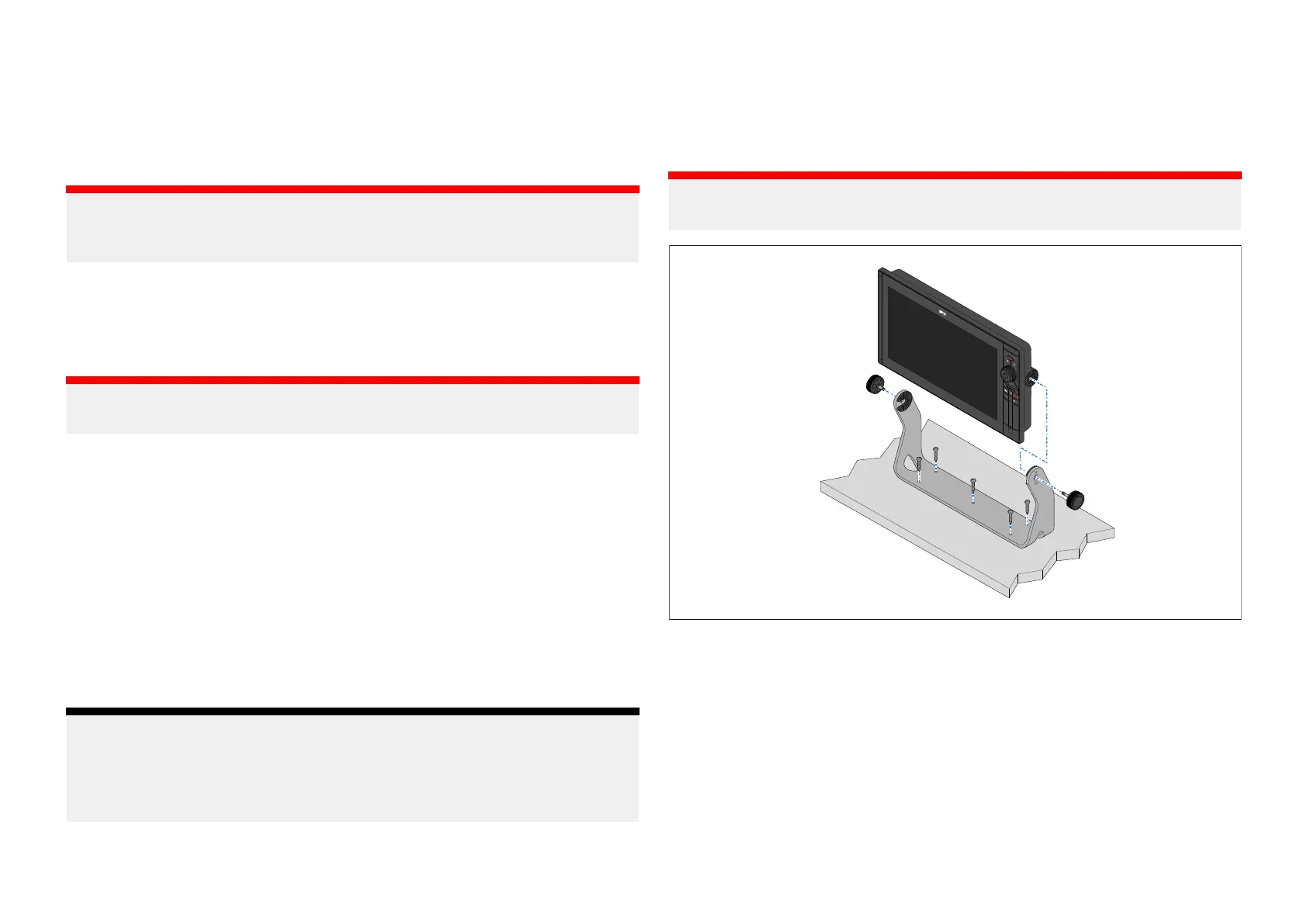
Trunnionbracketmounting
Oncethedisplayhasbeenpreparedusingtheinstructionsandparts
supplied,itcanbemountedusingthetrunnionbracketasfollows:
Note:
Fixingstosecurethetrunnionbrack ettoamountingsurfacearenot
provided.5xself-tappingscrewsarerequired.Thescrewsshouldbe
suitableforthemountingsurfacematerialandthe5.75mm(0.23in)
diametermountingholesinthetrunnionbracket.
Ensureyouhavechosenasuitablemountinglocationforyourdisplay
,which
hassufficientheadroomtoallowthedisplay’sangletobeadjusted,orthe
displaytoberemovedifnecessary.Ifinstallingthedisplay‘abovehead
height’,takeextracaretoensuretheknobsaretightenedsufficientlyto
preventthemcominglooseduetovibrationwhenunderway.
Important:
2personinstallationisrequired.
1.Checktheundersideofthemountingsurfacetoensurenodamagewill
becausedbydrilling.
2.Checkthethicknessofthemountingsurfacetoensureitissufficientto
supportthedisplay
.
3.UsingtheTrunnionbracketasatemplate,markanddrillthe5xpilot
holesonthemountingsurface.
4.SecuretheTrunnionbrackettothemountingsurfaceusingyour
self-tappingscrewsandanappropriatescrewdriver.
5.Onepersonshouldalignthetrunnionholesinthesideofthedisplaywith
theholesinthetrunnionbracket.
Installation43
 Loading...