29
www.renishaw.com
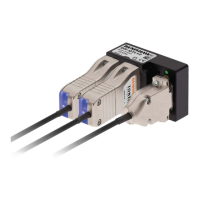
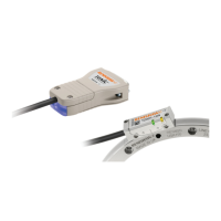
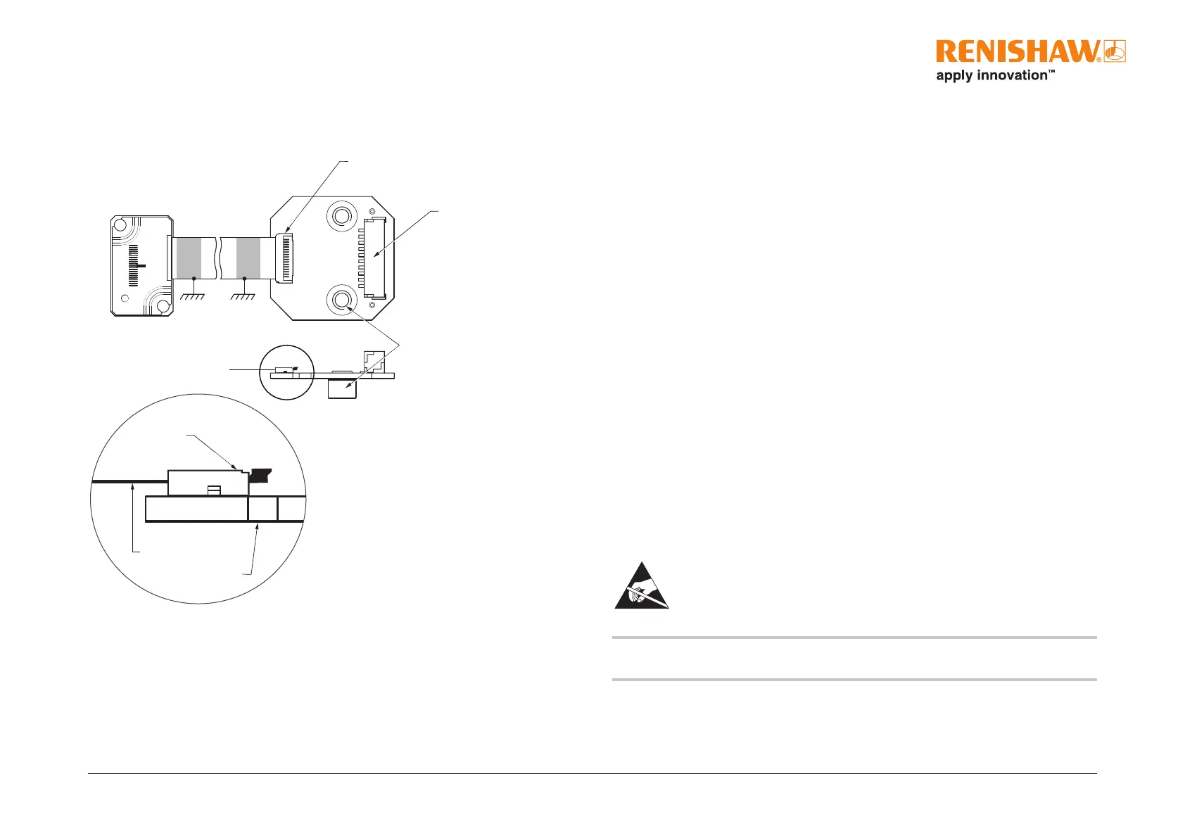
ACi interface
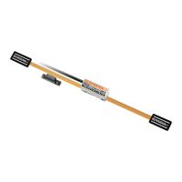
Ensure that the FPC cable being used has the following specications:
• 16 core
• Conductor pitch 0.5mm
• Minimum exposed conductor strip length 1.5mm
• Maximum exposed conductor strip length 2.5mm (to ensure isolation from the body).
Contact your local Renishaw representative for more information regarding FPC design requirements.
2 mounting holes M3 through
JST output connector
FPC input connector
Pin 1
Pin 1
NOTE: The FPC cable must be connected to the readhead before tting the lid. The lid is secured
by the readhead mounting screws.
Approved ESD precautions must be followed at all times during readhead
and interface electrical connection.
FPC variant
Shielding
For optimum performance:
• Ensure 100% shielding
• Ground the mounting brackets, readhead and FPC cable clamp
• Ensure continuity of all shields
• Maximise the distance between the encoder and motor cables
• Provide appropriate strain relief at the readhead and interface
• The ACi should be contained within a shielded enclosure
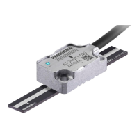
Mounting
The ACi can be mounted to customers’ system using two M3 screws or two M2.5 screws for
through mounting.
Output
The output connector is a 10-way JST, GH crimp connector with 1.25mm pitch. It is suitable for
cable size 26 to 30 AWG. See page 56 for pin-out information.
Connection
For information on inserting and removing the FPC cable to the ACi and readhead, see page 27.
Detail A
PCB
FPC cable
FPC input
connector
Detail A
 Loading...