35
www.renishaw.com
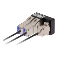
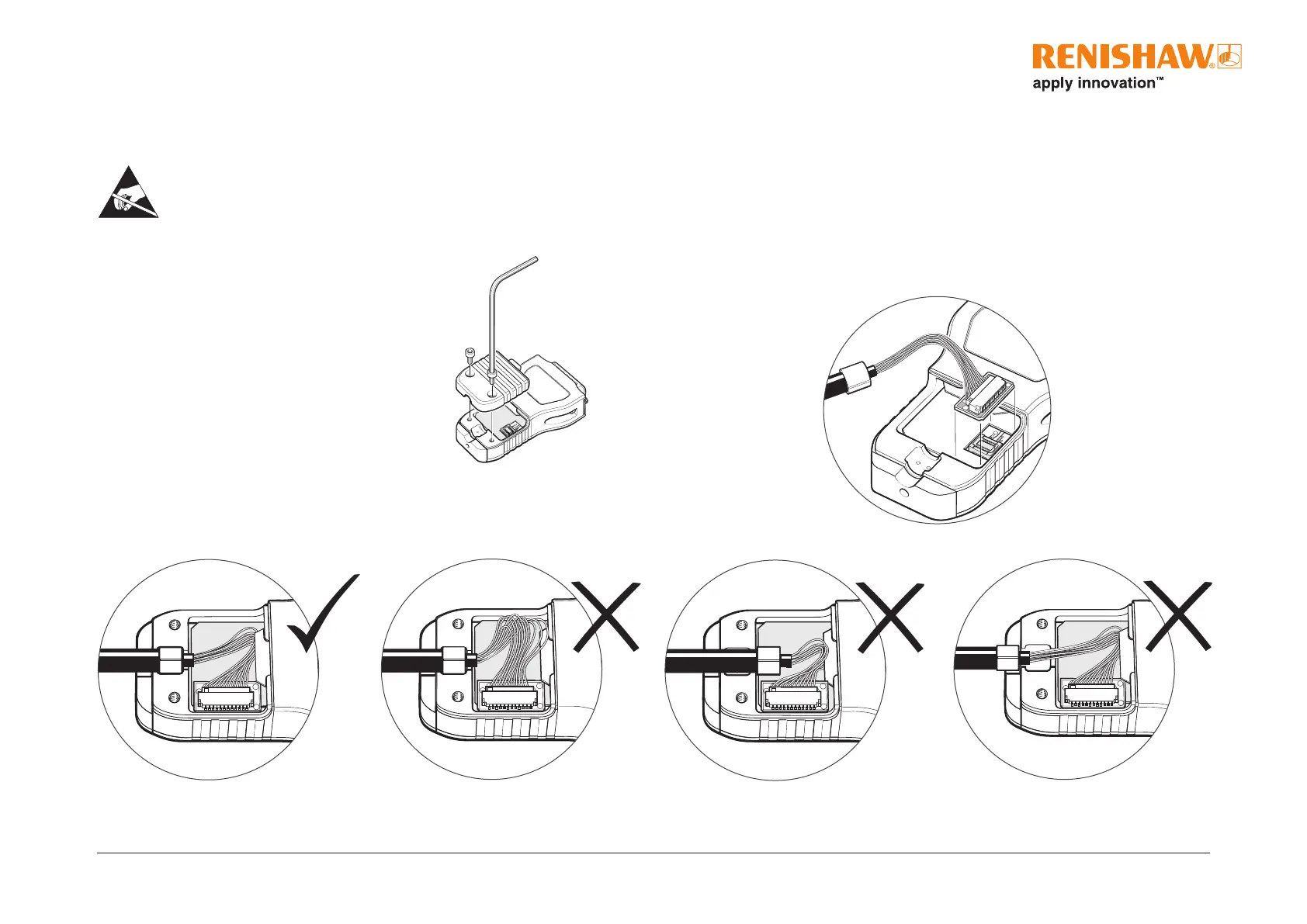
Ti interface
3. Ret the cover plate, ensuring the cable ferrule is located in the recess on the inside, and no wires are trapped under the cover plate.
1. Remove the cover plate as shown (two M2.5 hex head screws).
2. Taking care not to touch the pins, plug the connector into the socket in the interface, ensuring correct orientation as shown.
4. Proceed with ‘Readhead mounting and alignment’ on page 37 and ‘System calibration’ on page45.
Approved ESD precautions must be followed at all times during readhead and interface electrical connection.
The readhead is connected to the Ti interface via a small, rugged interboard connector to allow for easy feed-through during installation.
Connecting the readhead
 Loading...