14 Publication: AMEN00064 2019‑03‑07
Revolution
®
HVLS Fan • Rogue
®
HVLS Fan Installation/Service/Owner's Manual Rite‑Hite
®
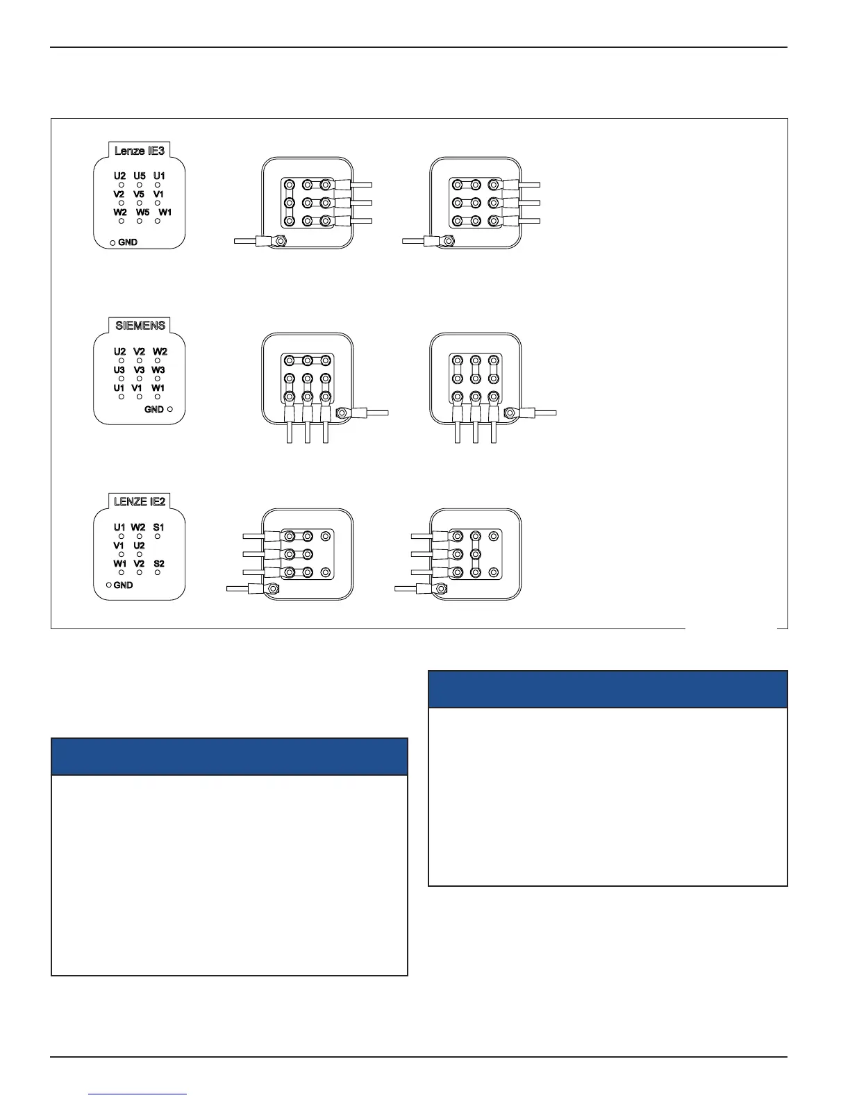
ELECTRICAL
Motor Wiring
GND
U V W
GND
GND
GND
GND GND
U
V
W
U
V
W
U
V
W
U
V
W
U V W
LENZE IE3 230V
WYE-WYE
SIEMENS 230V
WYE-WYE
LENZE IE2 230V
DELTA
LENZE IE3 460V
WYE
SIEMENS
460V WYE
LENZE IE2 460V
WYE
NORD 460V
WYE
SIEMENS 575V
WYE
NORD 575V
WYE
<1002M170.SLDDRW.pdf>
NOTE: Use stranded
copper conductors only,
minimum 75 C. To maintain
4X rating, use only UL listed
4X ttings. Do not make
conduit connections through
the top of enclosure. To
reduce risk of electric shock,
an earth ground connection
must be eld installed to the
Green/Yellow control box
ground terminal.
The fan motor will receive three‑phase power from the fan
control box even if single‑phase power is provided to the
control box. Remove the cover from the motor junction
box. Change the wire leads as necessary for high or low
voltage (Figure 12).
NOTICE
Do Not use solid core wiring of any size or insulation
class for controller output/motor leads.
To connect the fan control box to the motor use these
(14AWG Minimum Gauge) acceptable
wire types:
Unshielded cable:
‑ THHN/THWN Minimum 600V 90°C
Shielded XLPE VFD cable:
‑ Belden 29501
‑ AlphaWire V16014
Conduit Restrictions
NOTICE
Power supply lines for a controller May share the
same conduit with Power supply lines for 1 or
more additional controllers.
Power supply lines for a controller and output/motor
leads for the same controller or another controller
May Not share the same conduit.
The conduit with the incoming power and the conduit
with the power going to the motor should be separated
by a minimum of 6in [150mm].
Figure 12
 Loading...