Program a Function Block Diagram
12 Rockwell Automation Publication 1756-PM009G-EN-P - February 2018
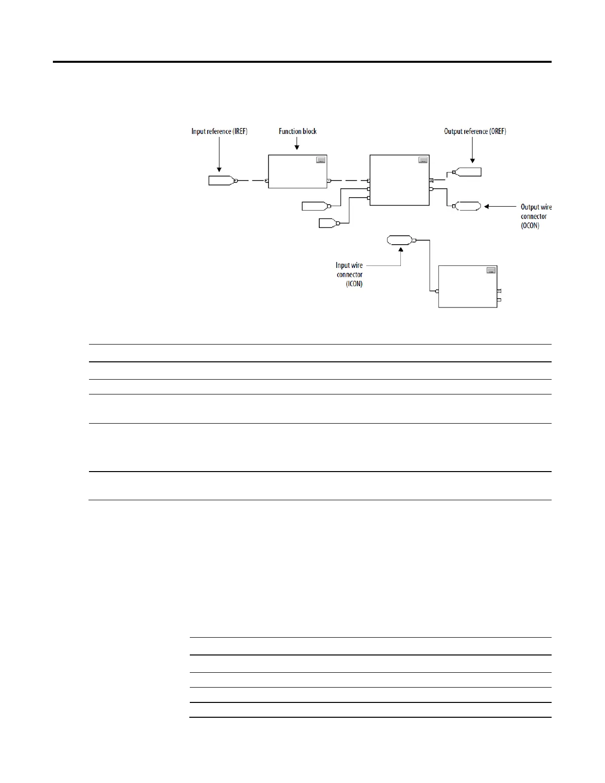
To control a device, use these elements.
To choose the function block elements, use these guidelines.
If you want to: Then use this element:
Supply a value from an input device or tag Input reference (IREF)
Send a value to an output device or tag Output reference (OREF)
Perform an operation on an input value or values and
produce an output value or values
Function block
Transfer data between function blocks when they are:
• Far apart on the same sheet.
• On different sheets within the same routine.
Output wire connector (OCON) and an input wire
connector (ICON)
Disperse data to several points in the routine Single output wire connector (OCON) and multiple input
wire connectors (ICON)
Each function block uses a tag to store configuration and status information
about the instruction.
• When you add function block instruction, the Logix Designer
application automatically creates a tag for the block. Use this tag,
rename the tag, or assign a different tag.
• For IREFs and OREFs, create a tag or assign an existing tag.
For a: Specify:
Tag
tag_name
Bit number of a larger data type
tag_name.bit_number
Member of a structure
tag_name.member_name
Element of a one dimension array
tag_name[x]
block elements
for an element

 Loading...


