Program a Function Block Diagram
Rockwell Automation Publication 1756-PM009G-EN-P - February 2018 25
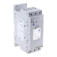
Wire (connect) two elements together by clicking the output pin of the first
element and clicking the input pin of the other element. A green dot shows a
valid connection point.
Item Description
Output pin of the first element
Input pin of the second element
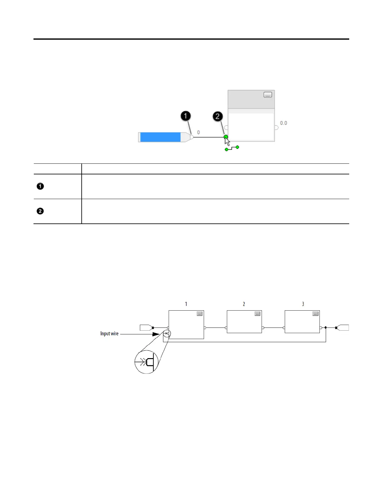
When there are a group of blocks in a loop, identify which block executes
first. The Assume Data Available indicator marks the input wire that creates
the loop (the feedback wire). It defines the data flow within the loop.
• To define a wire as an input wire, right-click the wire and click
Assume Data Available.
The arrow indicates that the data serves as input to the first block in the loop.
Assume Data Available
indicator

 Loading...