Program a Function Block Diagram
18 Rockwell Automation Publication 1756-PM009G-EN-P - February 2018
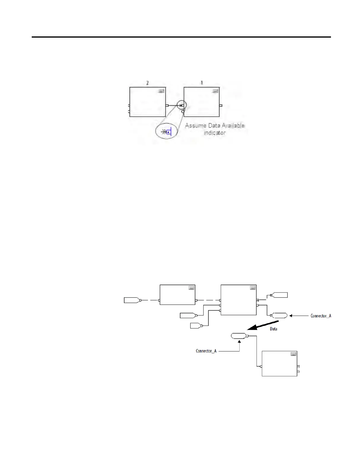
Use the Assume Data Available indicator to produce a one scan delay
between blocks. In this example, block 1 executes first. It uses the output
from block 2 that was produced in the previous scan of the routine.
A function block routine executes in this order.
1. The controller latches all data values in IREFs.
2. The controller executes the other function blocks in the order
determined by how they are wired.
3. The controller writes outputs in OREFs.
Like wires, connectors transfer data from output pins to input pins. Use
connectors when:
• The elements that you want to connect are on different sheets within
the same routine.
• A wire is difficult to route around other wires or elements.
• You want to disperse data to several points in the routine.
To use connectors, use these rules.
• Each OCON requires a unique name.
• For each OCON, you must have at least one corresponding ICON, such
as an ICON with the same name as the OCON.
delay
connectors

 Loading...


