Program a Function Block Diagram
Rockwell Automation Publication 1756-PM009G-EN-P - February 2018 29
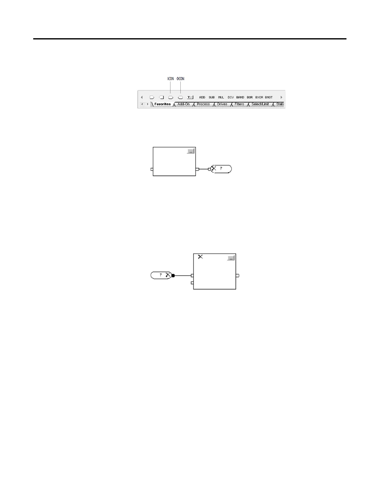
Use an output wire connector (OCON) or input wire connector (ICON) to
transfer data between sheets or in complex wiring situations.
1. Add an OCON and place it near the output pin that supplies the value.
2. Wire the OCON to the output pin.
3. Double-click the operand area of the OCON.
4. In the box, type a name that identifies the connector and press Enter.
1. Add an ICON and place it near the input pin that gets the value from
the corresponding OCON.
2. Wire the ICON to the input pin.
3. Double-click the operand area of the ICON.
4. In the box, click the down arrow and click the name of the OCON that
supplies the value to this connector.
5. Click Enter or click a blank spot on the diagram.
Edit the name of an input wire connector or an output wire connector in a
routine.
1. Right-click the operand area of the desired ICON or OCON, and click
Rename Element.
2. In the box, type or select a new name and press Enter.
an OCON and ICON
connector

 Loading...