Program a Function Block Diagram
Rockwell Automation Publication 1756-PM009G-EN-P - February 2018 15
The new tagA value of 50.9 is not used by any IREFs in this routine until the
start of the next scan.
The Logix Designer application automatically determines the order of
execution for the function blocks in a routine.
• When you verify a function block routine.
• When you verify a project that contains a function block routine.
• When you download a project that contains a function block routine.
Define the order of execution by wiring function blocks together and
indicating the data flow of any feedback wires, if necessary.
If function blocks are not wired together, it does not matter which block
executes first. There is no data flow between the blocks.
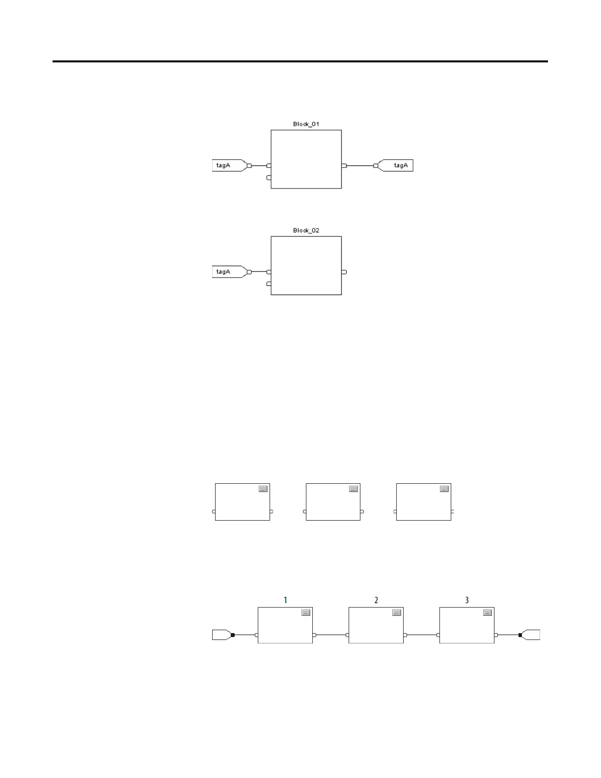
If the blocks are wired sequentially, the order of execution moves from input
to output. The inputs of a block require data to be available before the
controller can execute that block. In this example, block 2 has to execute
before block 3 because the outputs of block 2 feed the inputs of block 3.
The order of execution is only relative to the blocks that are wired together.
The two groups of blocks in this example are not wired together. The blocks

 Loading...


