Program a Function Block Diagram
28 Rockwell Automation Publication 1756-PM009G-EN-P - February 2018
4. Press Enter or click a different spot on the diagram.
You can assign a constant value instead of a tag value to an input parameter.
Make the value visible on the diagram and in
reports
Use an IREF on page 28
Change the value online without editing the
routine
Enter a Value in the Tag of a
Block on page 28
Complete these steps to assign a value to an IREF.
1. Add the IREF to the routine. For instructions on adding an element, see
Add a function block element on page 22
.
2. Wire the IREF to the input pin that gets the value. For instructions on
wiring elements together, see Wire elements together on page 25
.
3. Double-click the operand area of the IREF.
4. In the box, type the value and press Enter.
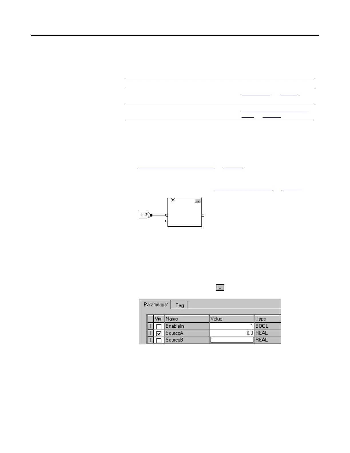
Complete these steps to assign a value to a parameter when on wire connects
to its pin.
1. In the block, click Properties .
2. On the Parameters tab, in the Value box of the desired parameter,
type the value.
3. Click OK.
immediate value
(constant)
of a block

 Loading...