EasyManua.ls Logo

Rockwell Automation Allen-Bradley Logix 5000 User Manual

Rockwell Automation Allen-Bradley Logix 5000
33 pages
To Next Page IconTo Next Page
To Previous Page IconTo Previous Page
Page #21 background imageLoading...
Page #21 background image
Program a Function Block Diagram
Chapter 1
Rockwell Automation Publication 1756-PM009G-EN-P - February 2018 21
Operator request inputs to an instruction are always cleared by the instruction
when it executes. This lets operator interface work with these instructions by
setting the desired mode request bit. You do not have to program the operator
interface to reset the request bits. For example, if an operator interface sets
the OperAutoReq input to a PIDE instruction, when the PIDE instruction
executes, it determines the appropriate response and clears the
OperAutoReq.
Program request inputs are not normally cleared by the instruction because
these are normally wired as inputs into the instruction. If the instruction
clears these inputs, the input would get set again by the wired input. There
might be situations where you want to use other logic to set the Program
requests to be cleared by the instruction. In this case, set the
ProgValueReset input and the instruction always clears the Program mode
request inputs when it executes.
In this example, a rung of ladder logic in another routine is used to one-shot
latch a ProgAutoReq input to a PIDE instruction when a push button is
pushed. Because the PIDE instruction automatically clears the Program mode
requests, you do not have to write any ladder logic to clear the ProgAutoReq
input after the routine executes. The PIDE instruction receives only one
request to go to Auto every time the push button is pressed.
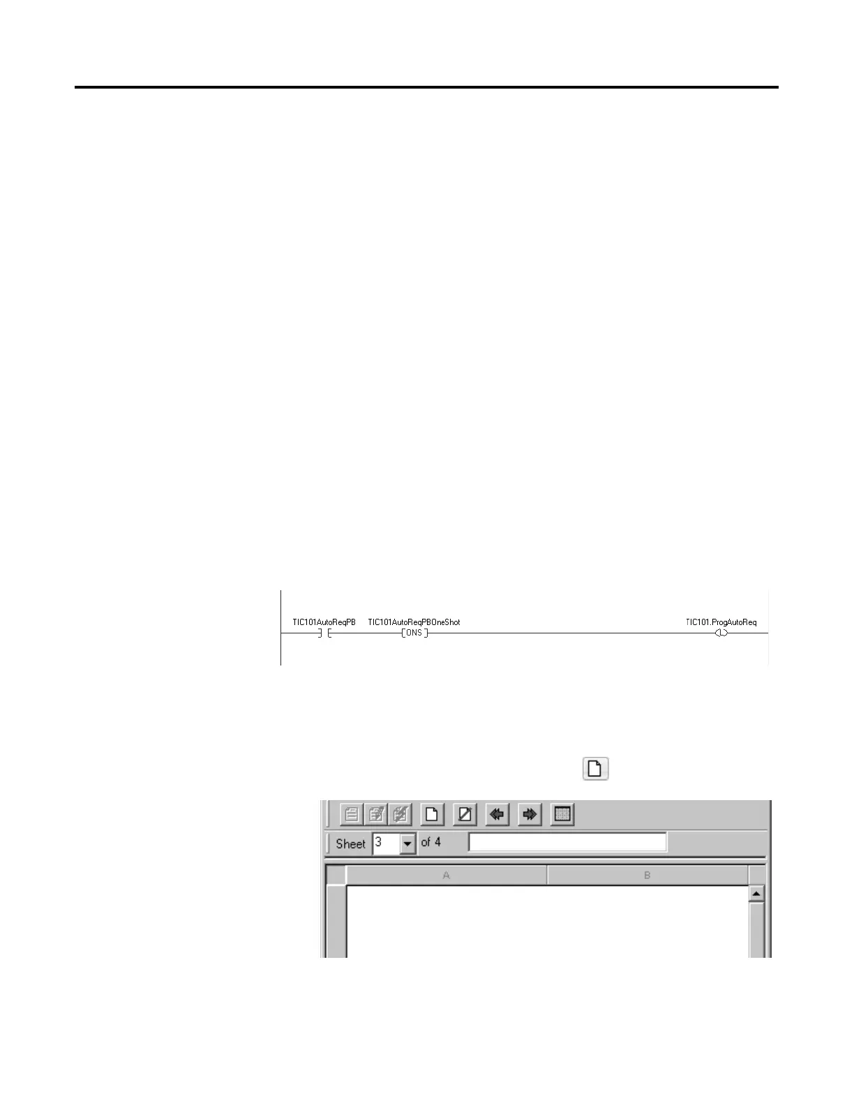
Example: When the TIC101AutoReq button is pressed, one-shot latch ProgAutoReq for the PIDE
instruction TIC101.
TIC101 is configured with the ProgValueReset input set, so when the PIDE instruction
executes, it automatically clears ProgAutoReq.
To add a sheet to a function block routine:
1. On the Sheet toolbar, click Add Sheet .
Add a sheet
Question and Answer IconNeed help?

Do you have a question about the Rockwell Automation Allen-Bradley Logix 5000 and is the answer not in the manual?

Rockwell Automation Allen-Bradley Logix 5000 Specifications

General IconGeneral
BrandRockwell Automation
ModelAllen-Bradley Logix 5000
CategoryController
LanguageEnglish

Summary

Important User Information

Safety Warnings and Precautions

Details critical safety warnings including explosion, injury, and electrical hazards.

Summary of Changes

Global Changes Overview

Identifies changes applicable across the manual.

New Features Summary

Lists recently added or enhanced features.

Preface

Studio 5000 Environment Introduction

Introduces the Studio 5000 Automation Engineering & Design Environment.

Additional Resources and Legal Information

Provides links to related documents, legal terms, and software notices.

Warranty and Contact Information

Covers product warranty, environmental compliance, and support contact details.

Chapter 1: Program a Function Block Diagram

Routine Organization with Sheets

Explains organizing routines with sheets for navigation.

Function Block Elements

Details the elements used to control devices in FBD, like IREF, OREF, ICON, OCON.

Tag Naming Conventions

Guides on creating and assigning tag names for function block elements.

Defining Execution Order

Explains how to define the sequence of block execution via wiring.

Data Latching with IREFs

Describes how IREFs latch data for function block scans.

Determining Execution Order

Explains how the Logix Designer application determines block execution sequence.

Resolving Feedback Loops

Illustrates how to resolve feedback loops in function block diagrams.

Resolving Data Flow Between Blocks

Provides guidance on data flow indicators for multiple wires connecting blocks.

Creating a One Scan Delay

Shows how to implement a one scan delay using the Assume Data Available indicator.

Using Connectors (OCON/ICON)

Explains the purpose and rules for using output and input connectors.

Program and Operator Control

Details how to manage instruction control between program and operator interfaces.

Adding a New Sheet

Step-by-step guide to add a new sheet to a function block routine.

Adding Function Block Elements

Instructions on adding various elements like IREF, OREF, etc., from the toolbar.

Creating Text Boxes for Notes

Explains adding text boxes for clarifying FBD elements.

Managing Language Switching

Discusses options for supporting and switching project documentation languages.

Showing and Hiding Pins

Details how to show or hide pins in function block properties.

Wiring Elements Together

Guides on connecting elements by wiring output to input pins.

Marking Wires with Assume Data Available

Explains marking feedback wires to define loop data flow.

Creating and Assigning New Tags

Step-by-step guide to create and assign a new tag to an element.

Assigning Existing Tags

Instructions for assigning an existing tag from the Tag Browser.

Assigning Immediate Values (Constants)

Explains how to assign constant values directly to parameters.

Using IREFs for Value Assignment

Details the process of assigning values to IREFs.

Entering Values in Block Tags

Describes entering values directly into block tags via wire connections.

Adding Output and Input Connectors (OCON/ICON)

Guides on adding and configuring OCON and ICON elements.

Renaming Wire Connectors

Explains how to rename ICON or OCON elements individually.

Renaming Connector Groups

Describes how to rename multiple connected elements simultaneously.

Verifying Function Block Routines

Guides on using the Verify function to check for errors in routines.

Rockwell Automation Support

Installation Assistance and Returns

Provides support for product installation and return procedures.

Documentation Feedback

Instructions for submitting feedback on the manual.

Related product manuals