Program a Function Block Diagram
24 Rockwell Automation Publication 1756-PM009G-EN-P - February 2018
offline and import it back into the project. Once you enable language
switching, you can dynamically switch between languages.
Project documentation that supports multiple translations within a project
includes:
• Component descriptions in tags, routines, programs, user-defined data
types, and Add-On Instructions.
• Equipment phases.
• Trends.
• Controllers.
• Alarm Messages (in ALARM_ANALOG and ALARM_DIGITAL
configuration).
• Tasks.
• Property descriptions for modules in the Controller Organizer.
• Rung comments, SFC text boxes, and FBD text boxes.
For more information on enabling a project to support multiple translations
of project documentation, see the online help.
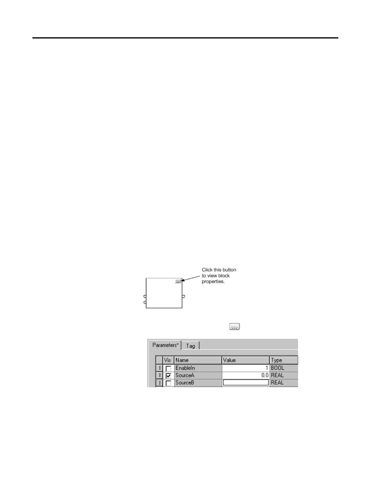
When you add a Function Block instruction, the block appears with a set of
pins for the default parameters. The rest of the pins are hidden. You can
show or hide a pin on the Parameters tab in the Properties dialog box.
1. In the block, click Properties .
2. In the Properties dialog box, on the Parameters tab, clear the Vis
check box to hide the pin. Select the Vis check box to show the pin.
3. Click OK.
Show or hide a pin

 Loading...