BRP-Rotax
Maintenance Manual
72-00-00
page 38
May 01/2007
Effectivity 912/914 Series
Edition 1 / Rev. 0
d02622
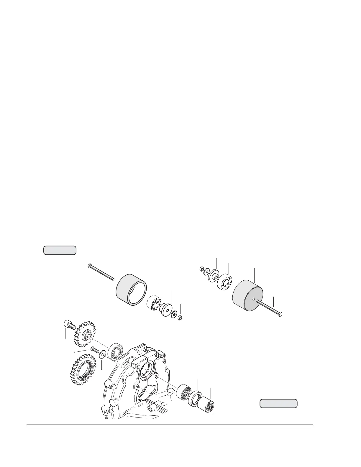
3.9.9) Vacuum pump drive installation
See Figs. 72-34, 72-35 and 72-36.
Lubricate new needle sleeve (3). Position puller cap (10), part no.
876489, on gearbox side, place press-in insert, part no. 877579, (11)
onto the needle sleeve and fix with the hex. nut (12). Turning the hex.
screw (13) clockwise presses the needle sleeve in completely.
The ball bearing is pressed in with the same procedure, but the puller
cap (10), part no. 876489, is fitted on the pump flange side and the
press-in insert (14), part no. 877595, is used.
Then the new oil seal (9) in pressed in using insertion jig, part no.
877276, and greased. Apply LOCTITE 221 to the sunk screw (7) M5x12
and the washer (8) for ball bearing fixation and tighten.
■ CAUTION : The length of allen screw (6) M8x14 must never be
altered, as otherwise the screw will collide with the drive
shaft of the vacuum pump.
Fit vacuum pump gear (4) and fix drive sleeve (5) with holder, part no.
242660. Apply LOCTITE 221 to allen screw (6) M8x14 and turn it in.
Fig. 72-35
Fig. 72-36
00253
00254
13
14
11
12
10
2
3
12
10
13
00252
8
9
4
5
6
7