Effectivity 912/914 Series
Edition 1 / Rev. 0
80-00-00
page 9
May 01/2007
d02629
BRP-Rotax
Maintenance Manual
3.3) Electric starter — inspection of individual parts
See Figs. 80-3, 80-4, 80-5 and 80-6.
◆ NOTE: The following work steps apply to both starter models (HD and
standard starter).
After disassembly of starter, check the following parts:
Rotor
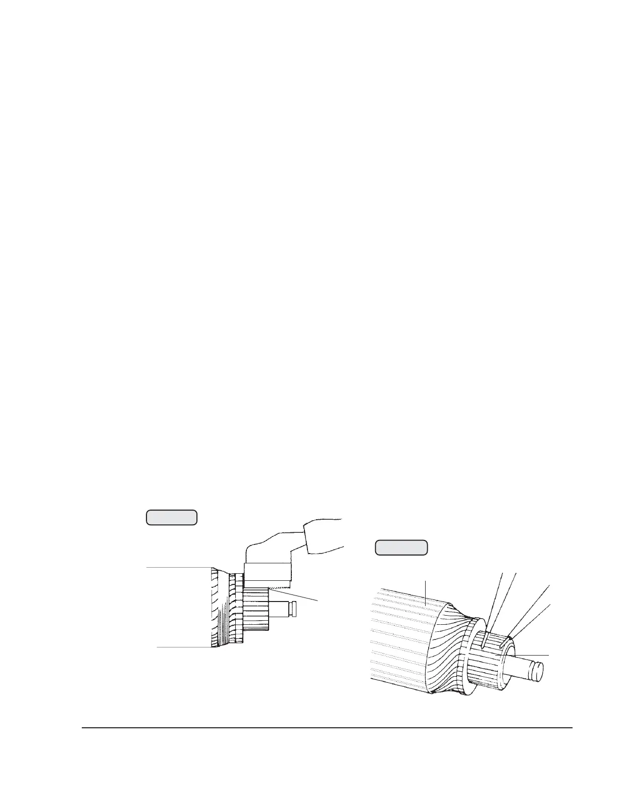
Clean commutator, check for run out, carry out visual inspection, if necessary
fine machine and undercut commutator ribs (7), see Fig. 80-5. The insulation
should be 0.5 mm (.02 in.) lower than the ribs.
▲ WARNING: During this machining process, material particles are released
and could possibly be inhaled.
Check rotor at 12 or 24 Volts with test lamp between commutator (8) and iron
core (9) for connection to ground. If the lamp lights up, replace rotor.
Check rotor coils for interruption at 2 or 4 Volts and an interposed ammeter
(measuring range 60 A), see Fig. 80-6. If there are great differences between
the individual ribs, the rotor must be replaced. If the rotor shows clear signs of
overheating, replace it.
Check ball bearing (10) 6002 Z. When replacing the rotor, fit it with the closed
side facing towards the middle of the rotor (open side (11) facing outward) to
prevent abraded particles penetrating the ball bearing. Inspect gear-tooth
system (12) and radial clearance of the rotor in the rotor bearing (3).
00233
8
9
Fig. 80-6
00232
7
Fig. 80-5