Effectivity 912/914 Series
Edition 1 / Rev. 0
74-00-00
page 3
May 01/2007
d02624
BRP-Rotax
Maintenance Manual
2) Systems description
2.1.) Electric system (alternators, ignition)
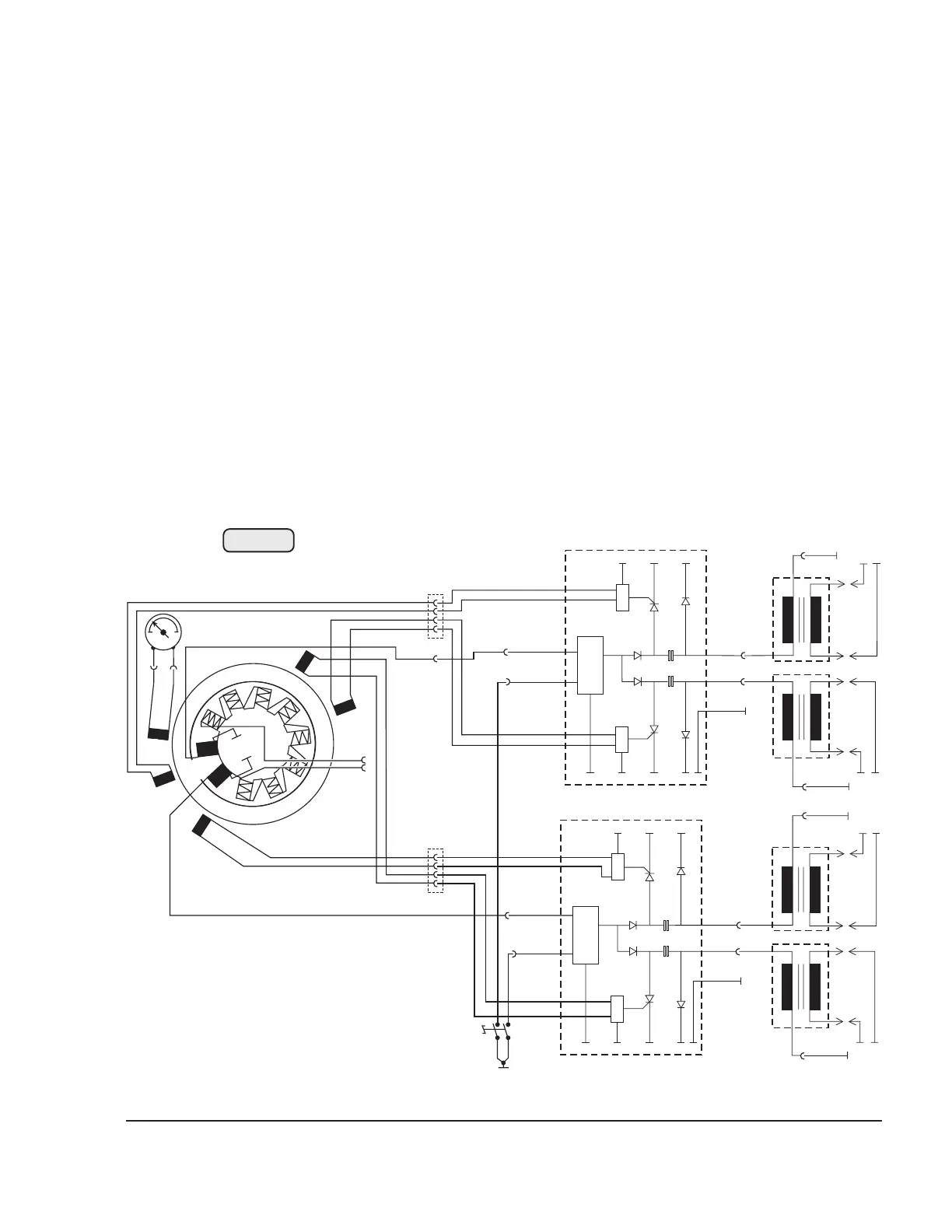
See Fig. 74-1.
ROTAX engines of the 912/914 Series are equipped with a breakerless dual
ignition system (DCDI-Dual Capacitor Discharge Ignition).
The ignition unit needs no external power supply.
Each of the two independent charging coils (1) located on the generator stator
supplies one of the two ignition circuits. The energy is stored in capacitors of the
electronic modules (2). At the moment of ignition, 2 each of the 4 external trigger
coils (3) actuate the discharge of the capacitors via the primary circuit of the dual
ignition transformers (4).
◆ NOTE: The 5th trigger coil (5) is provided for the rev counter signal.
E
E
E
T
E
W
W
R
R
R
R
B1/2
A3/4
B3/4
A1/2
Q
Ignition circuit A
Ignition circuit B:
07721
Fig. 74-1
5
1
3
3
3
3
2
2
4
4
4
4