8014868/YIF1/2020-10-19 • © SICK AG • Subject to change without notice 23
Mounting
6 Mounting
Mount distance sensor using suitable screws (M4). The screws are not
included in the scope of delivery.
• → See “Dimensions”, Chapter 13.1 on page 57
• → See “Technical data” (e.g. measuring range), Chapter 13 on page
56
• → See “Mounting accessories”, Chapter 14 on page 64
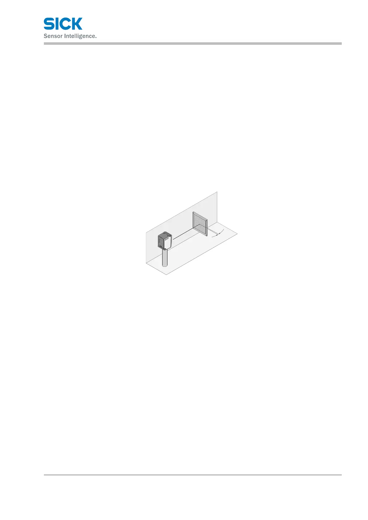
6.1 AligningtheDLandDRvariants
For the DL and DR variants, ensure that the reective tape is arranged
such that no direct surface reections reach the distance sensor.
Align the reective tape to the distance sensor in an angled position of
approx. 1° ... 3°. → See the gure below
ca. 1°...3°
Fig. 6: Correct alignment of the reective tape to the distance sensor
6.2 Alignment aid for infrared models
The infrared models DS35-B15821, DT35-B15851, DL35-B15852, and
DR35-B15822 have an alignment aid.
You can determine the exact position of the light spot with the aid of reec-
tive tape. Observe the typical light spot diameter of the distance sensor. →
See Chapter 13.2 on page 58
1. Position object.
2. Attach a small piece of reective tape to the center of the object for
performing alignment.
→ See the gure below
For simpler alignment, you can also rst use a reective strip in the
horizontal direction and then in the vertical direction.
3. Change the distance sensor to alignment mode. To do this, in run
mode, press the set pushbutton for longer than 5 seconds.
4. Perform coarse alignment. To do this, align the distance sensor roughly
in the direction of the reective tape.
 Loading...