8014868/YIF1/2020-10-19 • © SICK AG • Subject to change without notice 27
Electrical connection
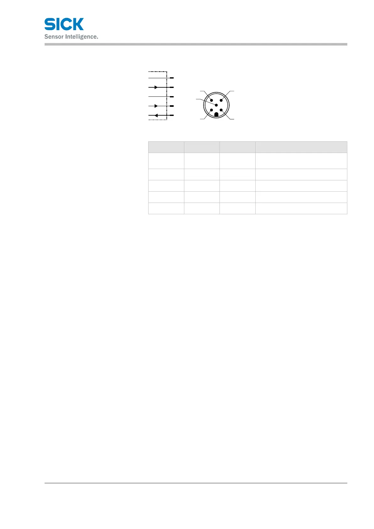
7.4.2 DS35 and DR35
L+
Q2
M
MF
1
2
wht
blu
gra
brn
3
5
Q1/C
4
blk
5
Fig. 9: DS35 and DR35 connection diagram, M12 plug, 5-pin
Contact Signs Wire color Description
1 L+ brown
Supply voltage:
→ See Chapter
13.4 on page 59
2 Q2 White Output signal switching device Q2
3 M Blue Supply voltage: 0 V
4 Q1/C Black Switching output Q1 / IO-Link
5 MF Gray Multifunctional input MF
Table 7: Description of M12 plug, DS35 and DR35
 Loading...