Electrical connection
26 © SICK AG • Subject to change without notice • 8014868/YIF1/2020-10-19
NOTE!
We recommend using pre-assembled cables for the
wiring. → For pre-assembled cables, see Chapter 14 on
page 64
All electrical connections of the distance sensor are congured as M12
round connectors.
The IP 65 or IP 67 protection class is only achieved using screwed plug
connectors.
By using EMC-compatible cable entries and wiring, you can avoid inter-
ference from devices such as switching power supplies, motors, clocked
drives, and contactors.
7.3 Connecting the distance sensor electrically
1. Ensure the voltage supply is not connected.
2. Connect the distance sensor according to the connection diagram. →
See Chapter 7.4 on page 26
3. Connect the supply voltage.
7.4 Connection diagrams
7.4.1 DT35 and DL35
L+
M
MF
2
wht
blu
gra
brn
3
5
Q1/C
4
blk
5
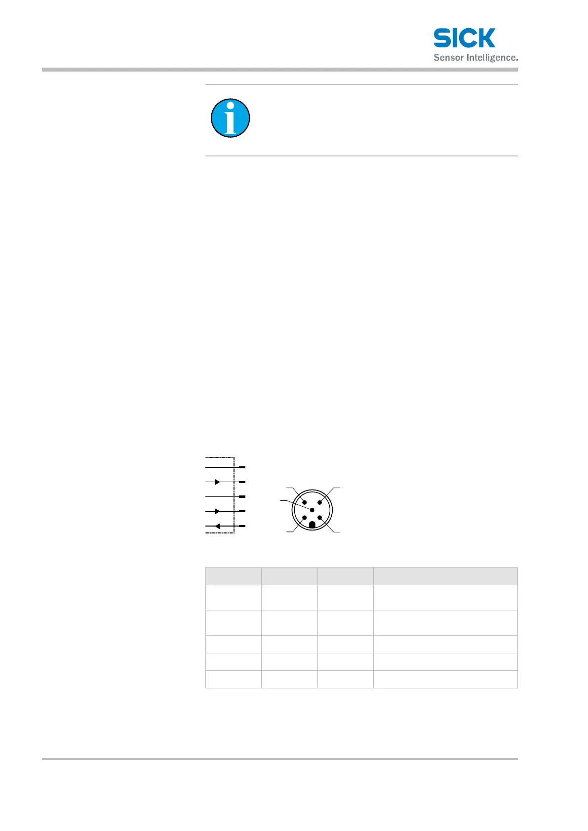
Fig. 8: DT35 and DL35 connection diagram, M12 plug, 5-pin
Contact Signs Wire color Description
1 L+ brown
Supply voltage:
→ See Chapter
13.4 on page 59
2 Qa/Q2 White Analog output Qa/
switching output Q2
3 M Blue Supply voltage: 0 V
4 Q1/C Black Switching output Q1/ IO-Link
5 MF Gray Multifunctional input MF
Table 6: Description of M12 plug, DT35 and DL35
 Loading...