Operation
112/121 Revision 05 • INSTALLATION AND OPERATING INSTRUCTIONS • 8DJH • 500-8067.9
22 Cable testing
22.1 Cable testing via cable plugs
Isolating and earthing the
feeder under test
➭ Disconnect the feeder under test.
➭ Make sure that the feeder in the opposite substation has also been isolated and secured
against reclosing.
➭ Verify safe isolation from supply.
➭ Earth the feeder.
Preparations ➭ Remove the cable compartment cover, see page 76, "Removing and mounting the cable
compartment cover".
➭ Remove the voltage transformers on the testing section and close the bushings in a
surge-proof way.
➭ Undo the screw-type cone at the T-plug or at the adapter.
➭ Fit cable test elements (e.g. measuring bolts) according to the operating instructions of the
plug manufacturers.
DANGER
High voltage! Danger!
➭ Isolate.
➭ Secure against reclosing.
➭ Verify safe isolation from supply.
➭ Earth and short-circuit.
➭ Cover or barrier adjacent live parts.
DANGER
Cable testing with connected cables represents a special stress for the isolating distance. If the
busbar of the switchgear under test or the opposite substation are live with operating voltage,
adequate measures must be taken in order to prevent overvoltages. Normally, the switch-
disconnector is not interlocked during the cable test.
➭ Fit switching prohibition signs.
➭ Secure the locking device (option) with a lock.
ATTENTION
The cables, cable plugs and voltage detecting systems may be damaged by too high test
voltages.
➭ Observe the specifications of the manufacturers of the cables, cable plugs and voltage
detecting systems (maximum test values).
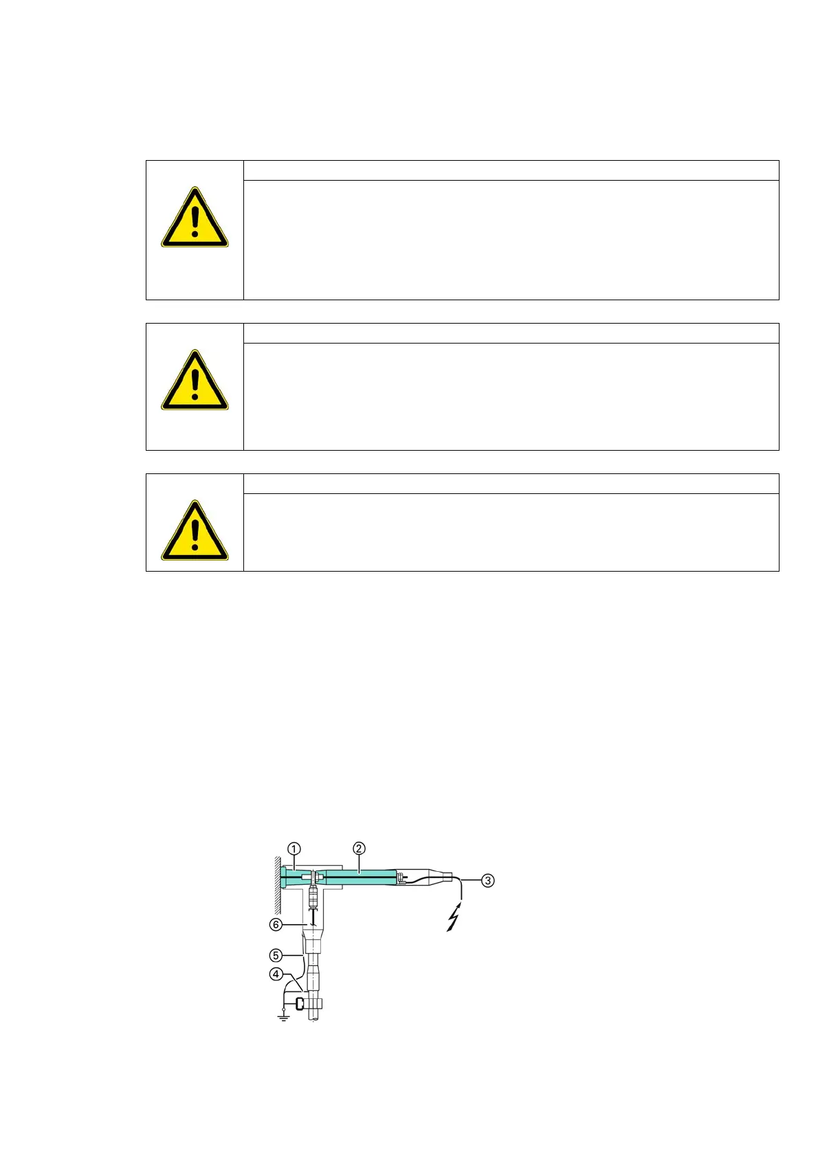
①
Bushing
②
Measuring bolt
③
Test lead
④
Earthing connection of cable
shield
⑤
Earthing connection of plug
⑥
T-plug
 Loading...