Description
26/121 Revision 05 • INSTALLATION AND OPERATING INSTRUCTIONS • 8DJH • 500-8067.9
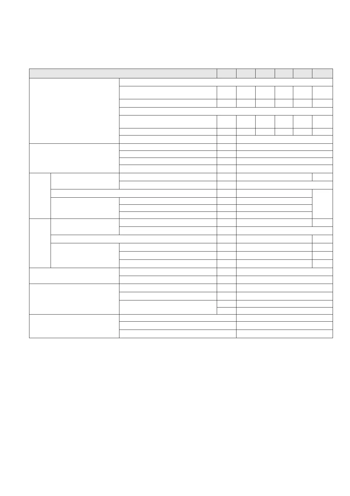
8 Technical data
8.1 General technical data
Rated voltage U
r
kV 7.2 12 15 17.5 24
Rated insulation level Rated short-duration power-frequency withstand voltage U
d
- phase-to-phase, phase-to-earth, open contact
gap
kV 20
28/42
1
36 38 50
- across the isolating distance kV 23
32/48
1
39 45 60
Rated lightning impulse withstand voltage U
p
- phase-to-phase, phase-to-earth, open contact
gap
kV 60 75 95 95 125
- across the isolating distance kV 70 85 110 110 145
Rated frequency f
r
Hz 50/60
Rated normal current I
r
2
Busbar A 630
Ring-main feeder A 400 or 630
Circuit-breaker feeder A 250 or 630
Transformer feeder A
200
3
50 Hz Rated short-time withstand
current I
k
Switchgear with t
k
= 1 s up to kA 25
20/21
1
Switchgear with t
k
= 3 s (design option) up to kA
20/21
1
Rated peak withstand current I
p
up to kA 63
50/52.5
1
Rated short-circuit making
current I
ma
Ring-main feeder up to kA 63
Circuit-breaker feeder up to kA 63
Transformer feeder up to kA 63
60 Hz Rated short-time withstand
current I
k
Switchgear with t
k
= 1 s up to kA 25
20/21
1
Switchgear with t
k
= 3 s (design option) up to kA
20/21
1
Rated peak withstand current I
p
up to kA 65
52/55
1
Rated short-circuit making
current I
ma
Ring-main feeder up to kA 65
52/55
1
Circuit-breaker feeder up to kA 65
52/55
1
Transformer feeder up to kA 65
52/55
1
Filling pressure (pressure values at 20 °C) Rated filling level p
re
(absolute) kPa 150
Minimum functional level p
me
(absolute) kPa 130
Ambient air temperature T Operation without secondary equipment °C
-25/-40
1
to +55/+70
1
Operation with secondary equipment
4
°C
-25/-40
1
to +55/+70
1
Storage and transport incuding secondary
systems
4
°C -25 to +70
°C -40 to +70 (option)
Degree of protection Gas-filled switchgear vessel IP 65
Switchgear enclosure
IP2X / IP3X
1
Low-voltage compartment
IP3X / IP4X
1
1
Design option
2
The rated normal currents apply to ambient air temperatures of max. 40 °C.
The 24-hour mean value is max. 35 °C (according to IEC/EN 62271-1/VDE 0671-1).
3
Depending on the HV HRC fuse-link
4
Depending on the secondary equipment used
 Loading...