Description
16/121 Revision 05 • INSTALLATION AND OPERATING INSTRUCTIONS • 8DJH • 500-8067.9
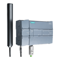
Basic scheme of fuse
tripping
The HV HRC fuse-links make SIBA (see page 37, "Selection of HV HRC fuse-links") release the
striker depending on the temperature and trip the switch-disconnector as early as in the
overload range of the fuses. Impermissible heating of the fuse box can be avoided in this way.
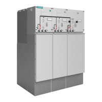
7.5 Cable connection
Cable connection for cable feeders, ring-main feeders and circuit-breaker feeders
Features For the cable connection, customary cable plugs for interface type C with bolted contact M16
are used according to EN 50181/DIN EN 50181.
Available designs:
• Screened (conductive) design (standard)
• On request: insulated design, e.g. as adapter for conventional sealing ends or mass-
impregnated cables (restrictions for site altitude and ambient climate)
For recommended cable plugs and possible connection cross-sections, see page 18, "Cable
plugs for single cable connection (interface type C)". The installation of other makes and types
is possible on request.
Fig. 10: Cable connection for ring-main feeder (example)
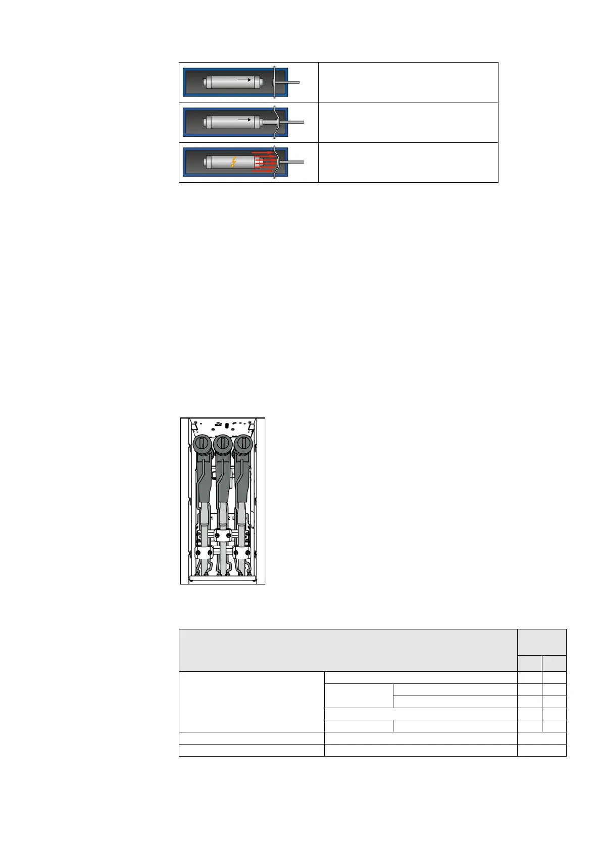
Connection possibilities for cable feeders, ring-main feeders and circuit-breaker feeders
HV HRC fuse-link in service condition
Fuse tripping through striker of HV HRC fuse-link
Fuse tripping due to sudden overpressure in the
fuse box
Cable Panel width
[mm]
310 430
Thermoplastic-insulated single-core
cable
1 cable per phase X X
1 cable per phase with surge limiter or surge arrester O O
with voltage transformer 4MT8 – –
2 cables per phase O O
2 cables per phase with surge limiter or surge arrester O O
Thermoplastic-insulated three-core cable 1 cable on request
Mass-impregnated cable 1 cable on request
X Standard O Option
 Loading...