119/221
Siemens Switzerland Ltd
User manual RVS61.843 CE1U2355en_02
HVAC Products 6 The settings in detail 23. November 2007
If, in the case of defrost through process reversal, it was not possible to successfully
defrost during “Defrost time max“, the controller aborts the defrost process and tries
again after the preheating phase (see “Duration defrost lock”).
The permitted number of defrost attempts is limited by “Numb defrost attempts max“
(2958).
Before the heat pump is allowed to resume heating mode after successfully defrosting
through process reversal, the “Dripping time evapor“ set here must elapse. The heat
pump resumes operation only on completion of this period of time and the fan is
switched on after a delay time preset by the supplier.
Frost protection for the heat pump
Frost protection for the heat pump leads to release of the heat pump as soon as the
flow or the return temperature falls below 5 °C. After both sensors have reached the
level of 6 °C, the heat pump’s release is maintained for 5 minutes.
If an electric immersion heater is installed in the flow, it is switched on for this period of
time.
In the case of a 3-stage electric immersion heater (K25 and K26), both relays are
energized.
Cooling
In the case of active cooling, the heat pump operates as a refrigeration machine by
reversing the process in the summer. Process reversal requires a heat pump equipped
with a 4-port valve (Y22) and a HP partial plant diagram which supports this function
(HP18, 19, 38, 39, 50, 51).
Cooling circuit (5711) and refrigeration (5807) can be in the form of a 2- or 4-pipe
system
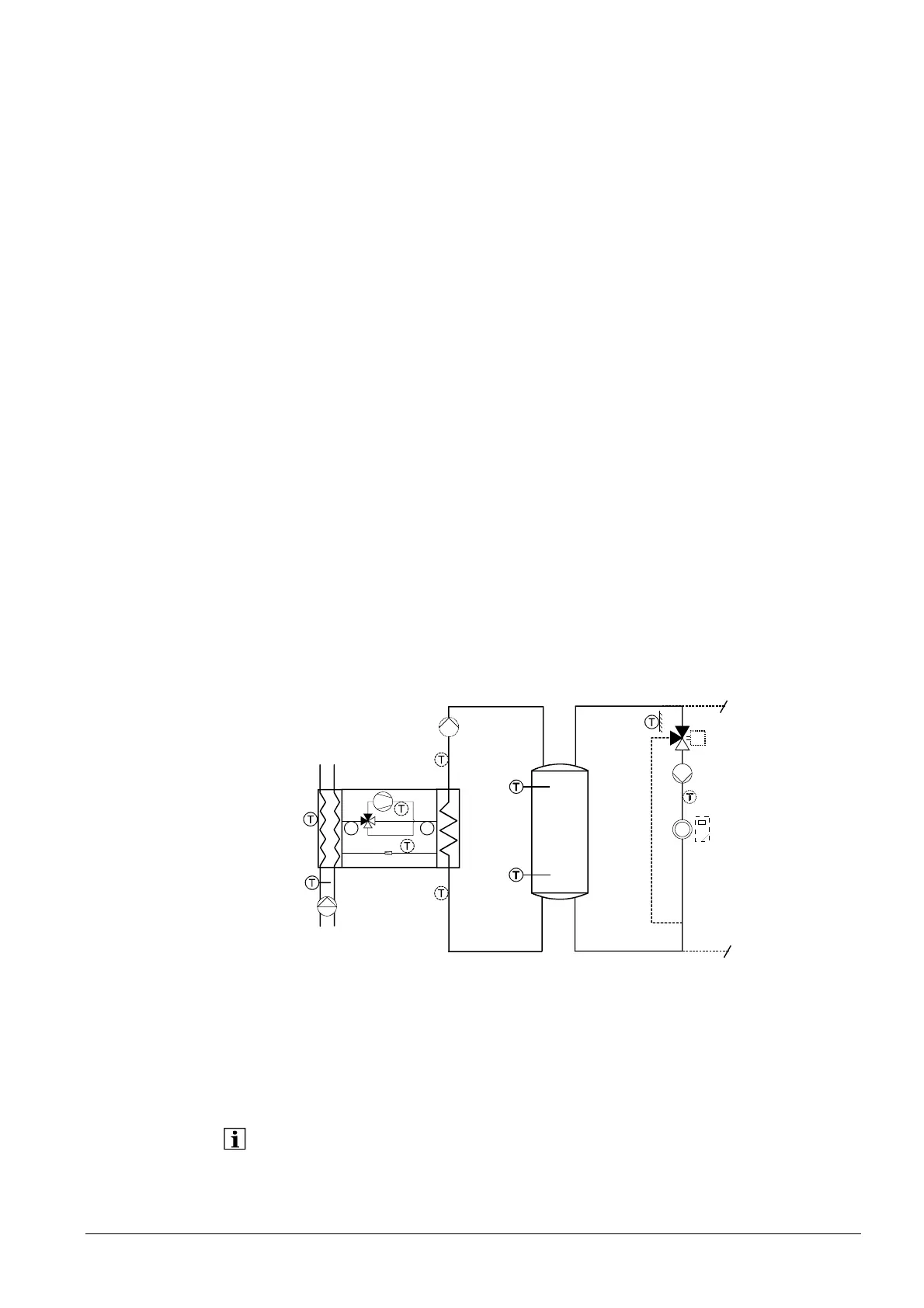
Application example:
B4
B41
B9
Y1/Y2
Q2
B1
B21
K1/E11
B71
B91
E9
P
P
B81
E10
B83
Q9
Y22
B84
K19
RG1
In the case of passive cooling, cooling is accomplished by letting the cold water
circulate through the system without putting a refrigeration source into operation. For
that purpose, the heat pump’s source pump and the cooling circuit are switched on.
Cooling circuit 1 (5711) and refrigeration (5807) can be in the form of a 4-pipe system.
The HP partial plant diagram must support passive cooling (HP 14, 15, 22, 23, 34, 35,
42, 43).
Passive cooling is not possible with air-to-water heat pumps.
Defrost time max
Dripping time evapor
Active cooling
Passive cooling
with brine-to-water or
water-to-water heat
pump
 Loading...


