191/221
Siemens Switzerland Ltd
User manual RVS61.843 CE1U2355en_02
HVAC Products 7 Plant diagrams 23. November 2007
7 Plant diagrams
The various applications are shown in the form of basic diagrams including heat source
/ refrigeration source variants and extra functions.
Basic diagrams can be implemented with standard outputs (excluding multifunctional
outputs).
Heat source / refrigeration source variants can be selected via appropriate parameter
settings.
To include extra functions, the multifunctional inputs and outputs must be appropriately
set.
7.1 Basic diagrams
The following plant diagrams can be preselected by entering a number (5700). The
plant diagram is the result of preselection plus the connected sensors.
The sensors contained in the selected plant diagram must be connected to ensure that
automatic sensor identification will not detect some other plant diagram. Components
shown with broken lines are optional.
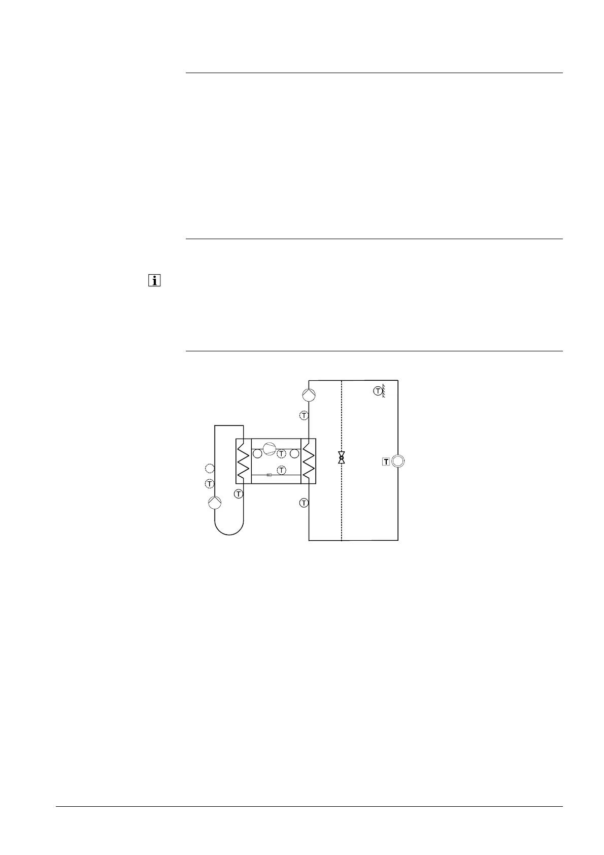
7.1.1 Plant diagram 1
Brine-to-water heat pump with pump heating circuit.
2358h9
B9
RG
B21
K1/E11
B71
B92
Q8/E14
B91
E15
P
Q2
E9
P
P
B81
E10
B83
 Loading...


