179/221
Siemens Switzerland Ltd
User manual RVS61.843 CE1U2355en_02
HVAC Products 6 The settings in detail 23. November 2007
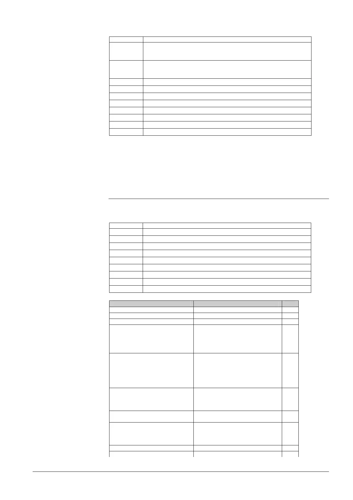
Input test E
Line no. Operating line
7889 Low-pressure switch E9
0 V
230 V
7890 High-pressure switch E10
0 V
230 V
7891 Compressor 1 overload E11
7911 Input EX 1
7912 Input EX 2
7913 Input EX 3
7914 Input EX 4
7915 Input EX 5
7916 Input EX 6
7917 Input EX 7
By selecting a setting from input test E, the relevant input will be displayed, enabling it
to be checked.
Display of 0 V means that there is no voltage and the respective input is currently
inactive. Display of 230 V means that voltage is present at the respective input so that it
is activated.
6.23 State of plant
The current operating state of the plant is visualized by means of status displays.
Messages
Line no. Operating line
8000 State heating circuit 1
8001 State heating circuit 2
8002 State heating circuit P
8003 State DHW
8004 State cooling circuit 1
8006 State heat pump
8007 State solar
8010 State buffer
8011 State swimming pool
Enduser (info level)
Commissioning, heating engineer
Limit thermostat has cut out Limit thermostat has cut out 3
Manual control active Manual control active 4
Floor curing function active Floor curing function active 102
Overtemp protection active 56
Restricted, boiler protection 103
Restricted, DHW priority 104
Restricted, buffer priority 105
Heating mode restricted 106
Forced discharging buffer storage tank 107
Forced discharging DHW 108
Forced discharging heat source 109
Forced discharging
110
Overrun active 17
Forced discharging
110
Opt start control + boost heating 111
Optimum start control 112
Boost heating 113
Heating mode Comfort Heating mode Comfort 114
Optimum stop control 115
Heating mode Reduced Heating mode Reduced 116
Frost protection room active 101
Frost protection flow active 117
Frost protection plant active 23
Frost protection active 24
Summer operation Summer operation 118
24-hour Eco active 119
State heating circuit
 Loading...


