178/221
Siemens Switzerland Ltd
User manual RVS61.843 CE1U2355en_02
HVAC Products 6 The settings in detail 23. November 2007
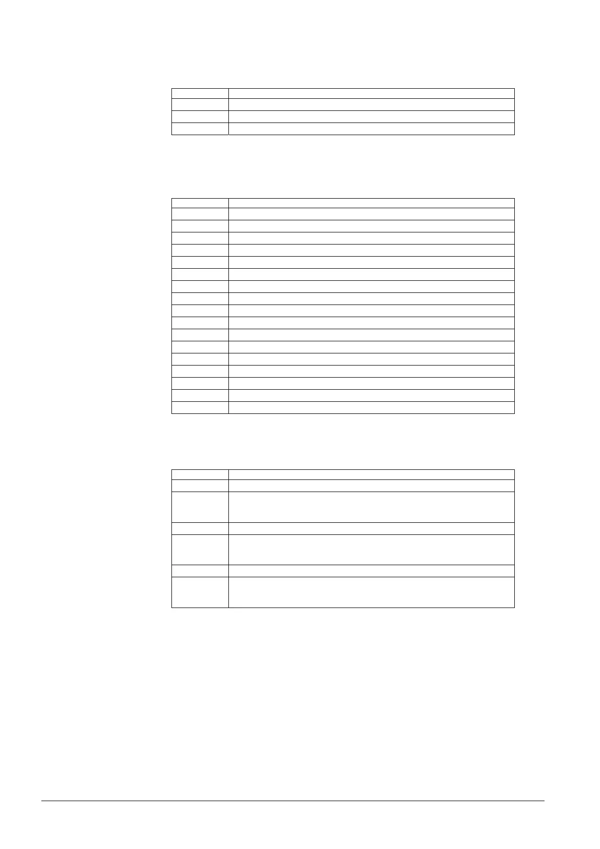
Output test UX / P1
By selecting a setting from output test UX / P1, an appropriate signal is delivered,
enabling it to be checked.
Line no. Operating line
7710 Output test UX
7711 Voltage signal UX
7714 PWM signal P1
Input test sensors
By selecting a setting from input test sensors, the relevant input is displayed, enabling it
to be checked.
Line no. Operating line
7730 Outside temp B9
7732 Flow temp B1
7750 DHW temp B3
7770 Flow temp HP B21
7771 Return temp HP B71
7772 Hot-gas temp B81
7775 Source inlet temp B91
7777 Sensor temp B92, B84
7820 Sensor temp BX1
7821 Sensor temp BX2
7822 Sensor temp BX3
7823 Sensor temp BX4
7824 Sensor temp BX3
7830 Sensor temp BX21 module 1
7831 Sensor temp BX22 module 1
7832 Sensor temp BX21 module 2
7833 Sensor temp BX22 module 2
The selected sensor values are updated within a maximum of 5 seconds.
The display is made with no measured value correction.
Line no. Operating line
7840 Voltage signal H1
7841 Contact state H1
Open.
Closed).
7845 Voltage signal H2
7846 Contact state H2
Open.
Closed).
7854 Voltage signal H3
7855 Contact state H3
Open.
Closed).
Shows the value of the pending voltage signal (DC 0…10 V).
Shows the current state of contact H1.
Input test H1, H2, H3
Voltage signal
H1, H2, H3
Contact state
H1, H2, H3
 Loading...


