139/221
Siemens Switzerland Ltd
User manual RVS61.843 CE1U2355en_02
HVAC Products 6 The settings in detail 23. November 2007
Mixing valve control
Line no. Operating line
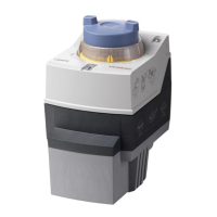
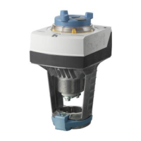
5544 Actuator running time
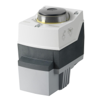
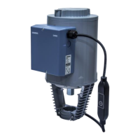
Setting the running time of the actuator used with the mixing valve.
6.18 Configuration
Procedure
First, make use of the presetting choices and enter the plant diagram that comes
closest to the plant in question. Then, modify manually the individual partial diagrams to
match them to the actual requirements.
After that, select the extra functions and make the fine-tuning via the operating lines of
the individual parameters.
Preselection of
plant diagram
Line no. Operating line
5700 Presetting
The plant diagrams shown in chapter “Applications“ can be preselected by entering a
diagram number. The plant diagram is the result of presetting plus the connected
sensors.
The sensors contained in the required plant diagram must be connected to ensure that
automatic sensor identification will not detect some other plant diagram.
Manual setting /
adjustment of partial diagrams
The plant diagrams consist of several partial diagrams.
The required partial diagrams can be used to manually produce the required final plant
diagram.
But it is also possible to modify and adjust partial diagrams of a plant diagram
generated via “Presetting” (5700).
A catalog with partial diagrams, which is separately available, contains the partial
diagrams implemented in the controller – classified according to groups. Also listed in
the catalog are the required operating lines which must be set to produce the
respective partial diagrams, plus the sensors required for the relevant partial diagram.
You can use operating lines 6212 - 6217 (see page 162) to check if your adjustments
led to the right partial diagram. The check no. shown there must accord with the
relevant components group.
ctuator running time
Presetting

 Loading...

