161/301
Siemens Building Technologies Basic Documentation LMV5... CC1P7550en
HVAC Products 8 Commissioning instructions for the LMV5... system 13.08.2004
The burner runs at ignition load or at the first burner stage. The positions of the actua-
tors can now be changed.
Menu level 1 Menu level 2 Menu level 3 Menu level 4 Menu level 5 Menu level 6
Params & Display
RatioControl
OilSettings
CurveParams
Curve Settings
Actuator
Positions
followed
not followed
It is recommended to use the function «Actuator positions followed» to set the switching
points and operating points of the second and third stage.
Menu level 1 Menu level 2 Menu level 3 Menu level 4 Menu level 5 Menu level 6
Params & Display
RatioControl
OilSettings
CurveParams
Curve Settings
Actuator
Positions
followed
not followed
————————
SetPointStage1
StartPointStage2
OffPointStage2
SetPointStage2
StartPointStage3
OffPointStage3
SetPointStage3
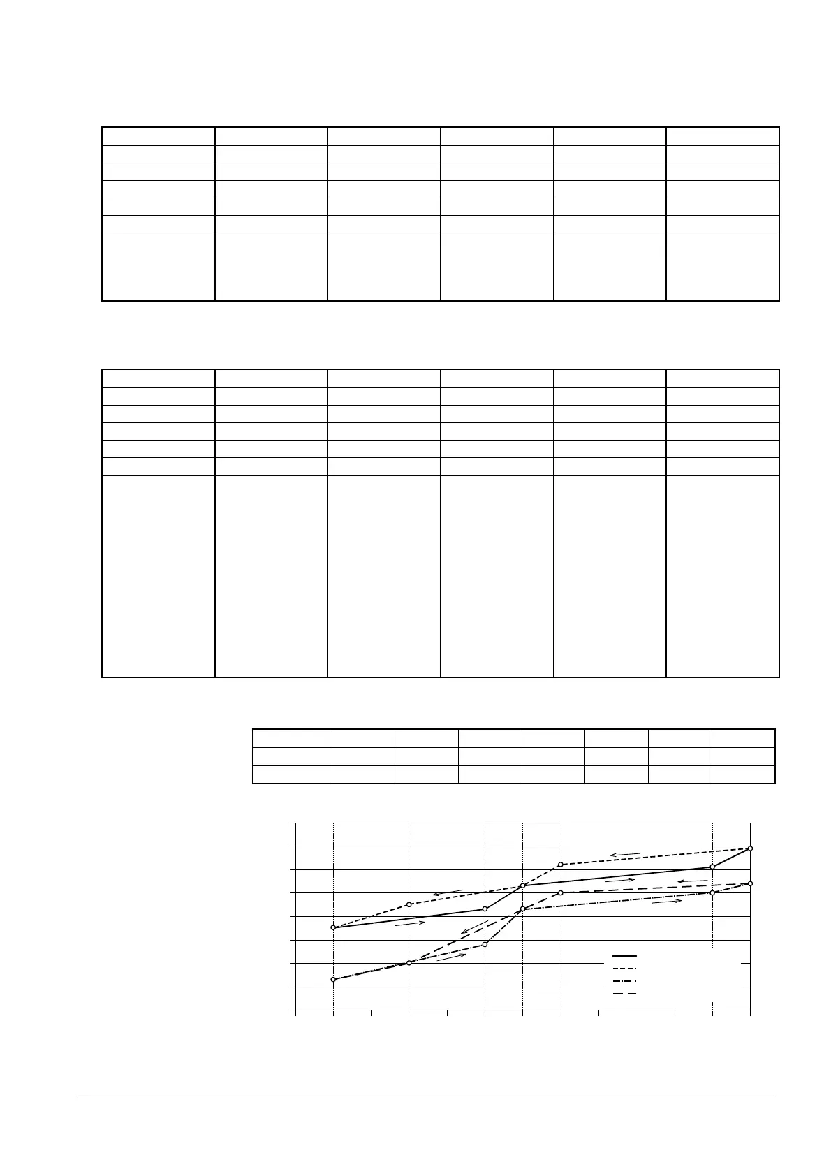
Example:
Stage S1 S2 on S2 off S2 S3 on S3 off S3
Air 35.0° 43.0° 45.0° 53.0° 61.0° 62.0° 69.0°
Aux 13.0° 28.0° 20.0° 43.0° 50.0° 50.0° 54.0°
80
45
Fuel / air ratio contol (multistage operation)
Position [°]
7550d27e/0704
70
60
50
40
30
20
10
0
70 100 %
Air actuator position «Down»
Auxiliary actuator «Down»
Air actuator position «Up»
Auxiliary actuator «Up»
V1 V2 down V2 up V2 V3 down V3 up V3
Load [%]
25. Setting the burner
stages
 Loading...
