253/301
Siemens Building Technologies Basic Documentation LMV5... CC1P7550en
HVAC Products 18 Addendum 3: Variable speed drive (VSD) module 13.08.2004
18.1 VSD module
A VSD can be connected to the VSD module integrated in the LMV5x.2...
The VSD is controlled via an analog current output and a potential-free release contact.
Evaluation of the alarm feedback signal from the VSD is accomplished with a 0...24 V
output. When activated, the LMV5x.2... will enter the safety phase.
Both motor speed and direction of rotation are acquired by an inductive sensor. The
asymmetric speed signal is checked for direction of rotation and plausibility.
The VSD module generates acceleration and deceleration ramps in accordance with the
parameters settings made on the LMV5x.2...
The motor speed is adjusted based on the same principle as that used with actuator ad-
justments. For this reason, the characteristic of the VSD must be linear. Filters, delay
and damping members must be removed.
The VSD module of the LMV5x.2... controls the motor speed to the setpoint. The control
range is limited to +15 % / -10 %.
If control range limitation becomes active, an appropriate display appears on the AZL5...
If that is the case over a longer period of time ( → «Safety Time Ratio Control»), the
LMV5x.2... will be shut down and the message «Special Position not reached» or
«Speed not reached» will appear.
Speed control is active for speeds ≥ 8 %.
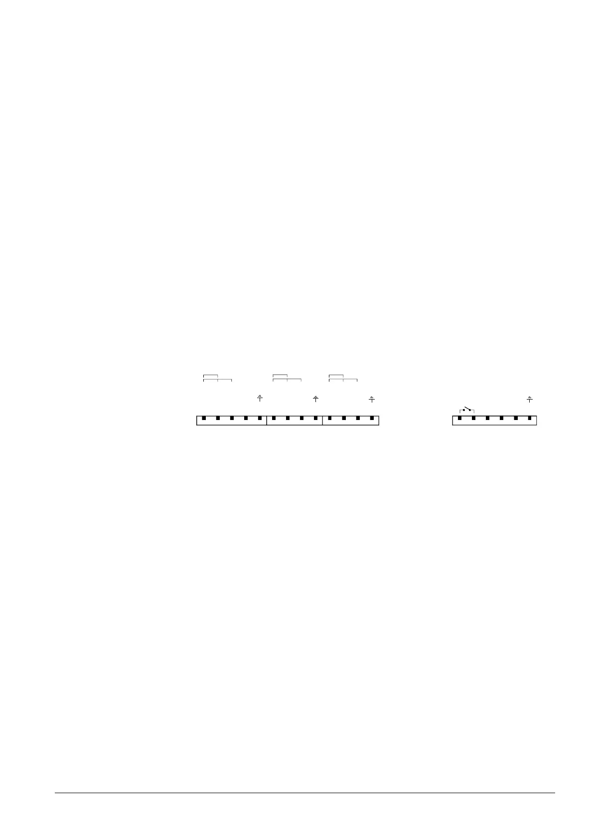
18.1.1 Inputs / outputs
MOTOR SPEED INPUT
OILGAS
1
X70
1
X71
FUEL COUNTER INPUT
1
X72
X73
1
FREQUENCY CONVERTER
Usensor
Pulse-IN
0
Reserve
FE
Usensor
Pulse-IN
0
FE
Usensor
Pulse-IN
0
FE
12-24VDC Alarm-IN
0/4-20mA Setpoint OUT
0
FE
Start-OUT
2 Wire
3 Wire-PNP
2 Wire
3 Wire-PNP
2 Wire
3 Wire-PNP
7550a11e/0704
The LMV5x.2... has a potential-free release contact for the VSD. This contact will be ac-
tivated when a motor speed other than zero is required.
Voltage: ≤ AC / DC 24 V (protective extra low-voltage)
Current: 5 mA to 2 A
The alarm input of the LMV5x.2... will be connected to the alarm output of the VSD. In
the event of an alarm, safety shutdown will be triggered as a minimum requirement.
Voltage active: DC 12...24 V (alarm ON)
Voltage inactive: < DC 4 V (alarm OFF)
This output is used for delivering the preselected speed setpoint to the VSD.
Current: 0 / 4...20 mA ≈ 0...105 % (→ «Standardization of Speed»)
Output load: max. 750 Ω (burden), short-circuit-proof
Resolution: 0,1 %
Cross-sectional area of wire: ≥ 0,1 mm
2
General
Connection diagram
Release contact
X73-1 / -2
Alarm input
X73-3
Analog output to
the VSD X73-4
 Loading...
