191/301
Siemens Building Technologies Basic Documentation LMV5... CC1P7550en
HVAC Products 12 Mounting, electrical installation and service 13.08.2004
12 Mounting, electrical installation and
service
•
The burner / boiler manufacturer must ensure degree of protection IP 40
through appropriate mounting
• Depending on the field of use, external requirements may impose more strin-
gent degrees of protection, which must then be observed
• When fitted, the maximum permissible ambient temperature may not be ex-
ceeded!
• The unit is designed for mounting inside the burner casing or in a control
panel
• The display and operating unit (AZL5…) has its own housing and can be
mounted in a suitable location (detached from the basic unit), e.g. away from
the burner or in the control panel door
• Condensation water may not drip on the unit, neither in operation nor while
service work is carried out!
• The power transformer is not integrated in the LMV5... and must be fitted by
the burner / boiler manufacturer in a suitable location
(Only the AGG5.2XX transformers specified by Siemens BT may be used!)
The entire RAST5 connection area
does not feature functional low voltage.
The RAST3.5 connection area on the unit’s small side offers functional low voltage.
•
When making the wiring, the functional low voltage section must be strictly
separated from the other sections to ensure protection against electric shock
hazard!
• Adequate protection against electric shock hazard on unused AC 230 V termi-
nals (RAST5) must be provided by fitting dummy plugs!
• To isolate the unit from the mains supply, a multipolar switch must be used.
• For wiring the bus users, only the cables specified by Siemens BT may be
used!
• The electrical contacts used by the external signal sources (DWmin, max, LC,
etc.) must be gold-plated silver contacts!
• The ignition cable must be run to the ignition electrode as directly as possible,
with no loops
It may never be laid parallel with or very close to other electrical cables.
7
5
5
0
v
0
2
Installation
Electrical connections
and wiring
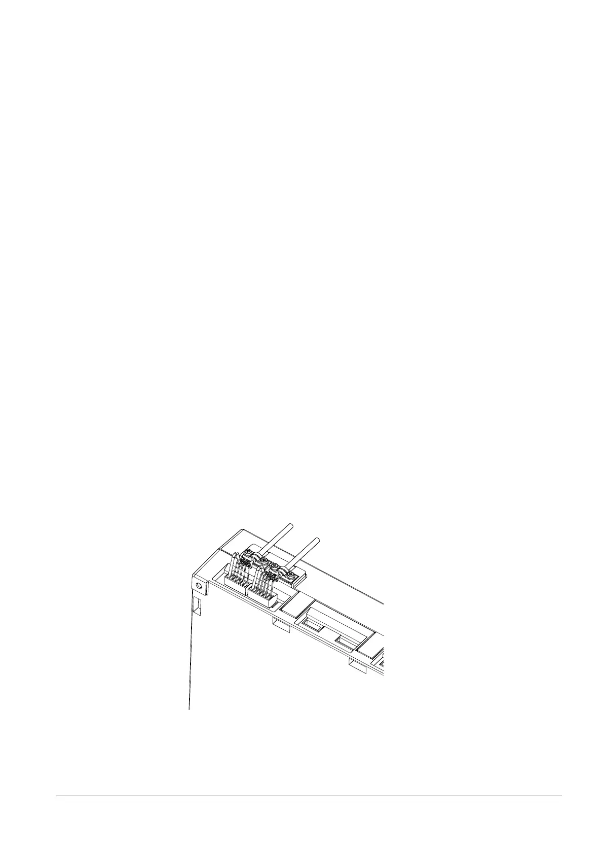
Connection of
LMV5... CAN bus
 Loading...
