59/301
Siemens Building Technologies Basic Documentation LMV5... CC1P7550en
HVAC Products 4 Burner control 13.08.2004
Assignment of times:
t0 Postpurge lockout position
Depending on the parameter, VP takes place:
between Ph62 and Ph70 or
/and
between Ph30 and Ph32 t01 MaxT_SafetyPhase
t10 MinTimeHomeRun
Signal ON Signal OFF Next phase t21 MinT_StartupRel
t22 FanRunupTime
01
00, Rep = 0
12, Rep > 0
t30 PrepurgePt1
t34 PrepurgePt3
t36 MinOnT_OilPump
t38 PreignitionT_Gas / Oil
Parameter direct start
Checking with controller on
Deviation → 10
No Rep. decrement t42 PreignitionT_Off
10 t44 Interval1 Gas / Oil
70 t52 Interval2 Gas / Oil
Without VP70 with VP80 t62 MaxTimeLowFire
62 t70 AfterburnTime
Stop, up to Ph – max. time → 01 t74 PostpurgeT1 Gas / Oil (tn1)
Stop, up to Ph – max. time → 10 t78 PostpurgeT3 Gas / Oil (tn3)
t80 VP_EvacTime
0 – 3 s
01
00, Rep = 0
12, Rep > 0
t81 VP_TimeAtmPress
t82 VP_FillTime
0 – 30 s
01
00, Rep = 0
12, Rep > 0
t83 VP_TimeGasPress
tmx1 MaxDampRunTime
0 – 3 s
01
00, Rep = 0
12, Rep > 0
tmx2 MaxT_StartupRel
tmx3 MaxT_CircHOil
Param.
79
10
TSA1 SafetyTime1
TSA2 SafetyTime2
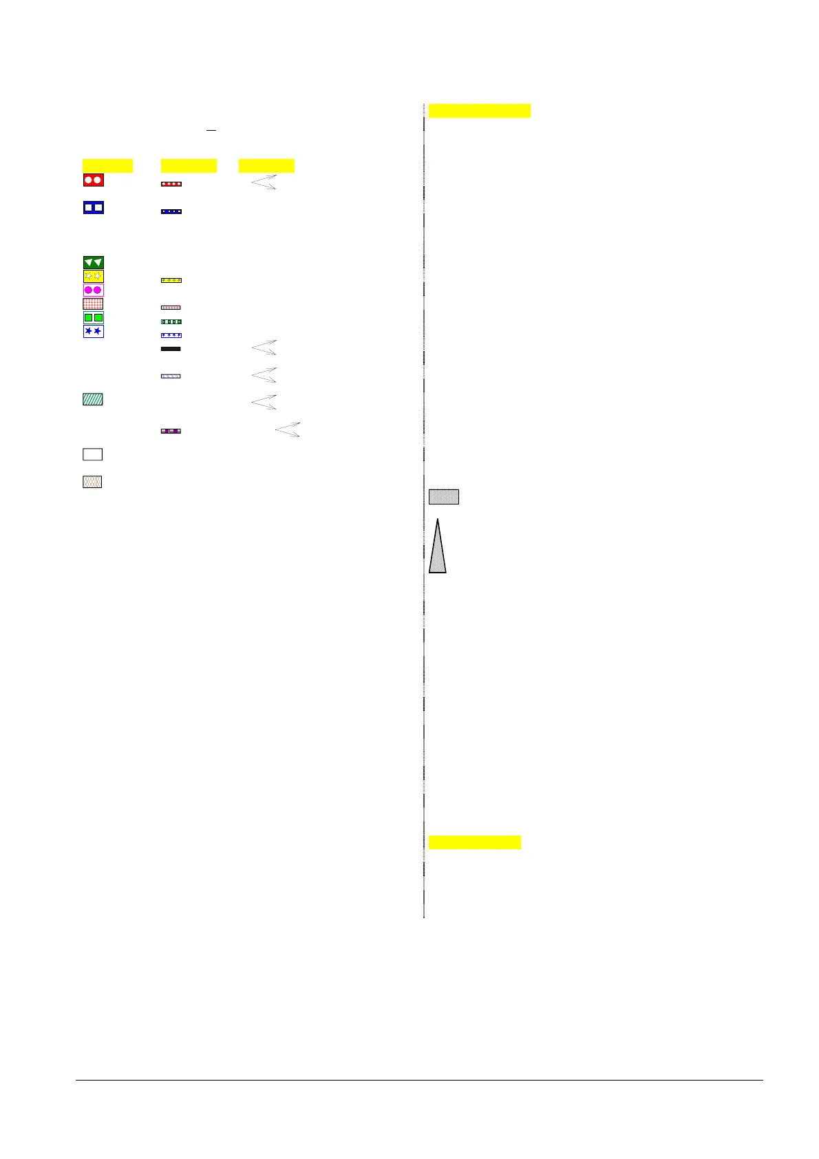
Input: don´t care
Output: OFF tv PrepurgeTime_Gas / Oil
Output: ON
Permissible positioning range
1) Parameter: With / without PM
2) Parameter: Short / long preignition time for oil only
Short / long oil pump – ON – time
3) Delayed shutdown within TSA1 + TSA2
4) Parameter: Output as startup signal / PM relief valve
In Standby: actuator can travel within the permissible po-
sitioning range, but is always driven to the home position.
Must be in the home position before changing the phase
5) Parameter: Normal / direct startup
0° Position as supplied (0°) Normal startup → sequential phase = 10
Direct startup → sequential phase = 79 90° Actuator fully open (90°)
(when R = ON)
6) Sequential phase = 24 FGR Flue Gas Recirculation
7) Only with valve proving during startup CPI Closed Position Indicator
8) Parameter: With / without alarm on prevention of startup AD Air damper
9) Parameter: With continuous purging PS-VP Pressure Switch-Valve Proving
FCC Fan Contactor Contact 10) Fan controlled as before
Running time when LOCK OUT = T_FanLockout LF Low-fire position
11) Parameter: With / without extraneous light test in STANDBY APS Air Pressure Switch
12) With valve proving during startup Startup phase 10 PS Pressure Switch
13) Parameter: Normal / continuous purging PoP Post-Purge position
Normal purging: Checking for off in 10, stop to HP Home Position
Ph-max time → 01 SR Safety Relay
Continuous purging: Checking for on in 10 and SLT Safety Limit Thermostat
12, Stop up to Ph-max time → 01 TL Temperature Limiter
14) Parameter: “OilPressureMin”, “akt_from_ts“ → no check IGN Ignition position
before TSA1 (LO, HO) or TSA2 (LOgp, HOgp)
15) Parameter: “GasPressureMin“, “deakt_xOGP“ → PSmin can Repetition counter:
be deactivated for oil programs with gas pilot
16) Parameter: “OilPumpCoupling“, “direct_coupl“ → SVoil has k) Heavy oil
to be connected to output “Oil pump / magnetic l) Restricted startup behavior
clutch“. Output is active when fan is on and for n) Restricted safety chain
another 15 s after fan is switched off
17) Parameter: “Start / PSvalve“, “PS_Reli_Inv“→ Output PS valve will be logically inverted
18) Parameter: “Alarm act / deact“, “deactivated“→ The alarm output can temporarily be deactivated (for current error only)
19) Parameter: Only with LMV52...: Continuous pilot gas / oil: Activated → Pilot valve is also activated in operation
20) Parameter: Only with LMV52...: Extraneous light, pilot phase, operating phase gas / oil → Separate flame supervision possible
21) Parameter: Only with LMV52...: DW-DK / CPI or StartReleaseGas → Parameter-dependent ON / OFF test
CPI Gas: OFF test for gas trains only
CPI Oil: OFF test for oil trains only
CPI Gas+Oil: OFF test for gas and oil trains
Legend to the sequence diagrams
 Loading...
